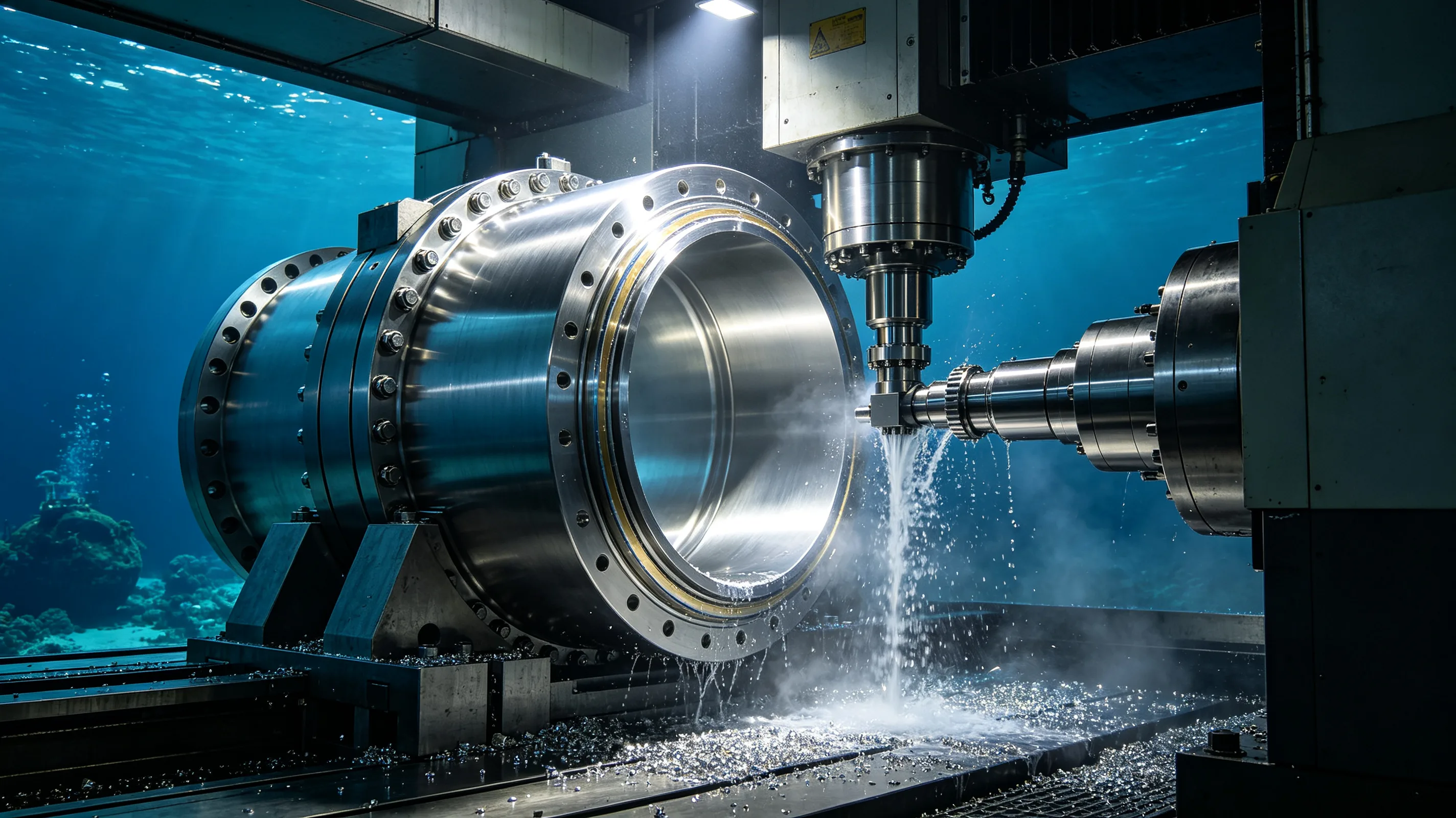
Subsea equipment operates at depths exceeding 3,000 m, where hydrostatic pressure surpasses 300 bar, temperatures approach 4 °C, and seawater chemistry drives galvanic corrosion rates that can exceed 0.5 mm/year in unprotected steel. Components such as connector hubs, valve bodies, manifold blocks, and ROV interface tooling must maintain dimensional stability and sealing integrity over 20–30 year service lives without intervention. This article examines the precision machining requirements specific to subsea equipment, covering material selection, tolerance regimes, surface protection strategies, and the manufacturing challenges that differentiate subsea component production from standard industrial CNC machining.
Executive summary
Precision machining for subsea equipment imposes a set of requirements distinct from aerospace or medical-device manufacturing. Deepwater components must resist hydrostatic collapse, maintain sealing surfaces within µm-level tolerances after years of corrosion exposure, and conform to industry codes such as API 6A, API 17D, NORSOK M-001, and ISO 13628. Titanium alloys — particularly Ti-6Al-4V (Grade 5) and Ti-6Al-4V ELI (Grade 23) — are increasingly specified for subsea applications due to their high specific strength, seawater corrosion resistance, and compatibility with cathodic protection systems. The machining challenges stem from the same material properties that make titanium valuable in subsea service: low thermal conductivity, high springback, and work-hardening tendency. Successful subsea component manufacturing requires process controls that integrate dimensional verification, surface integrity management, and corrosion-protection planning at every machining stage.
Material selection criteria for subsea precision machining
Subsea equipment specifications prioritize materials that resist pitting and crevice corrosion in chlorinated seawater environments, maintain mechanical properties at low temperature, and avoid galvanic coupling issues with adjacent cathodic protection anodes. Three material families dominate subsea component machining.
Titanium alloys
Ti-6Al-4V is specified for structural components requiring yield strengths above 830 MPa combined with fatigue resistance in seawater. Ti-6Al-4V ELI is preferred where fracture toughness is critical, such as pressure housing end caps and connector bodies. Grade 23 offers improved crack propagation resistance at temperatures below 10 °C compared to standard Grade 5. Both alloys require specialized tooling and coolant strategies during machining — carbide inserts with AlTiN coatings, high-pressure through-spindle coolant above 70 bar, and feed rates in the 0.08–0.15 mm/rev range to avoid work hardening.
Nickel-based alloys and superaustenitic stainless steels
Alloy 625 (UNS N06625) and alloy 718 are specified for subsea fasteners, springs, and valve trim where galling resistance is required. Superaustenitic stainless steels such as 6Mo (UNS S31254) and 7Mo grades offer cost-effective alternatives for less critical structural components, but their machining produces long, stringy chips that require chip-breaking tool geometries and high-pressure coolant to evacuate efficiently.
CP titanium and Grade 2
Commercially pure titanium (Grade 2) is used for seawater piping, instrument tubing, and non-structural housings where corrosion resistance rather than strength drives the material choice. CP titanium machines with lower cutting forces than Ti-6Al-4V but presents chip control challenges due to its high ductility. Sharp tool edges and positive rake geometries are essential to prevent built-up edge formation.
| Material | Typical Subsea Application | Yield Strength (MPa) | Corrosion Resistance in Seawater | Machinability Rating |
|---|---|---|---|---|
| Ti-6Al-4V (Grade 5) | Pressure housings, connector bodies, valve stems | 830–900 | Excellent (passive film) | Moderate |
| Ti-6Al-4V ELI (Grade 23) | Fracture-critical pressure components | 760–830 | Excellent (passive film) | Moderate |
| Alloy 625 (Inconel) | Valve trim, springs, fasteners | 415–690 | Excellent (high pitting resistance) | Low |
| 6Mo Superaustenitic | Manifold piping, instrument fittings | 345–450 | Very good | Moderate |
| CP Ti (Grade 2) | Seawater piping, instrument tubing | 275–410 | Excellent | Moderate |
| 316L Stainless | Low-stress bracketry, junction boxes | 170–310 | Moderate (crevice risk) | High |
Tolerance regimes and dimensional verification for subsea components
Subsea equipment tolerances are driven by sealing requirements, pressure-retaining fit, and interchangeability across multi-supplier assembly programmes. The relevant standards impose dimensional controls that exceed typical industrial machining specifications.
Critical sealing surface tolerances
Metal-to-metal seals used in subsea tree connectors, wellhead hubs, and flowline termination assemblies require sealing surface flatness within 0.013 mm (13 µm) and surface finish Ra ≤ 0.4 µm. Machining these surfaces on large-diameter components — flange faces up to 500 mm in diameter — requires thermally stable machine tools, controlled cutting fluid temperature within ±1 °C, and finish passes using wiper insert geometries at feed rates below 0.05 mm/rev.
Thread form and pitch diameter control
Subsea bolting threads conforming to API 7-2 or ISO 10423 specifications demand pitch diameter tolerance bands of ±0.025 mm for thread sizes up to M100. Thread milling rather than thread turning is preferred for titanium subsea components because it produces consistent flank surface finish and avoids the notch effects associated with single-point threading. Post-machining thread gauging using Go/No-Go plug gauges and pitch diameter measurement with thread micrometers is mandatory.
Dimensional verification methods
In-process dimensional verification for subsea components relies on a combination of techniques. Coordinate measuring machine (CMM) inspection with touch-trigger and scanning probes is used for housing features and bolt patterns. Air gauging is employed for bore diameters below 50 mm where CMM access is restricted. For large-diameter flange faces, laser trackers with ±0.015 mm accuracy over 2 m ranges verify flatness and parallelism. All inspection equipment must be calibrated to NIST-traceable standards with documented measurement uncertainty budgets.
Corrosion protection integration in the machining process
Subsea components require corrosion protection strategies that are planned at the machining stage rather than applied as post-process treatments. The machining process itself influences the effectiveness of subsequent surface protection.
Surface integrity and passive film formation
Titanium components exposed to seawater rely on a native oxide passive film (typically 2–5 nm thick) for corrosion resistance. Machining-induced surface damage — feed marks, laps, microcracks, and embedded carbide particles — can disrupt this film and initiate crevice corrosion. Finish passes at low feed rates with sharp tools minimise surface disruption. Chemical passivation per ASTM F86 removes free iron contamination and promotes uniform oxide growth. For titanium subsea components, passivation is performed after all machining operations and before any handling that could re-contaminate the surface.
Anodic protection and cathodic prevention interfaces
Subsea titanium components that contact cathodic protection anodes (typically aluminium-zinc-indium or zinc anodes) must be machined to avoid sharp edges where current density concentrates. External corners should be chamfered or radiused to at least R1 mm. Internal corners should have blend radii no smaller than R0.5 mm to avoid hydrogen uptake at high cathodic polarisation potentials. These geometry rules must be incorporated into the machining CAM programme at the programming stage, not added as post-process manual modifications.
Coating and surface treatment preparation
Components that receive additional corrosion protection — such as hard anodising (Type III per MIL-A-8625), thermal spray aluminium (TSA), or polymer-based barrier coatings — require surface preparation during machining. Surfaces to be coated should be machined to Ra 1.6–3.2 µm to provide adequate mechanical interlocking without creating stress raisers. Blasting media selection must avoid iron contamination; aluminium oxide or garnet media are specified, with post-blast surface cleaning and inspection for embedded particle removal.
Manufacturing challenges unique to subsea component machining
The combination of large workpiece mass, demanding tolerances, and difficult-to-machine materials creates manufacturing challenges that subsea component suppliers must address through facility planning and process engineering.
Workpiece stability and vibration control
Subsea components are typically machined from large forgings or bar stock — valve bodies exceeding 200 kg, connector hubs 300–500 mm in diameter, manifold blocks requiring 5-axis machining from multiple orientations. Workpiece clamping must resist cutting forces while avoiding distortion of thin-walled sections. Custom hydraulic or pneumatic clamping fixtures with programmable clamping force profiles are used. Where standard vises or chucks are inadequate, vacuum fixturing or magnetic clamping (for magnetic-permitting materials) is applied.
Chip evacuation and coolant management
Deep-hole drilling and pocketing operations on titanium subsea components generate long, continuous chips that pack in flutes and cause tool breakage if not evacuated. High-pressure through-spindle coolant at 70–100 bar breaks chips and flushes them from the cutting zone. Machine tools dedicated to subsea component production should have chip conveyors rated for titanium chip loads exceeding 500 kg per shift and coolant filtration systems capable of maintaining particle counts below 20 µm to prevent recirculation of fines that degrade surface finish.
Thermal distortion management
Large titanium components experience significant thermal expansion during extended machining cycles. A 400 mm diameter Ti-6Al-4V flange expands approximately 0.09 mm per 10 °C temperature rise. Machining cycles lasting multiple hours must account for ambient temperature variation and heat generated by the cutting process. Coolant temperature control within ±1 °C of the inspection lab temperature is standard practice. In-process probing cycles that measure feature positions and compensate for thermal drift are integrated into the CNC programme.
Quality documentation and traceability requirements
Subsea equipment procurement specifications typically require comprehensive manufacturing documentation that traces each component from raw material lot through final inspection.
Material traceability standards
All titanium subsea components must be accompanied by material test reports (MTRs) that document chemical composition, mechanical properties, and heat treatment parameters. Material marking using low-stress dot peen or laser marking is applied after rough machining to avoid marking-induced stress concentrations on finished surfaces. Marking content includes heat number, part serial number, and material grade per ASTM or AMS specification.
Dimensional inspection records
Inspection reports for subsea components typically include tabulated results for every critical dimension with actual measurement values, tolerance limits, and pass/fail status. Statistical process control data — feature-level Cpk values — are increasingly required by major subsea system integrators. Minimum acceptable Cpk for critical sealing features is 1.33; for pressure-retaining features it is 1.67.
NDT requirements integrated with machining
Non-destructive testing (NDT) is specified at defined manufacturing stages. Dye penetrant inspection (PT) per ASTM E1417 is applied to titanium components after rough machining to detect surface cracks and laps. Ultrasonic inspection (UT) per ASTM E2375 is performed on bar stock and forgings before machining to confirm internal soundness. Radiographic inspection (RT) is specified for weld-built subsea assemblies. Integration of NDT hold points into the machining schedule prevents rework sequences where a component is machined to finished dimensions before a subsurface defect is detected.