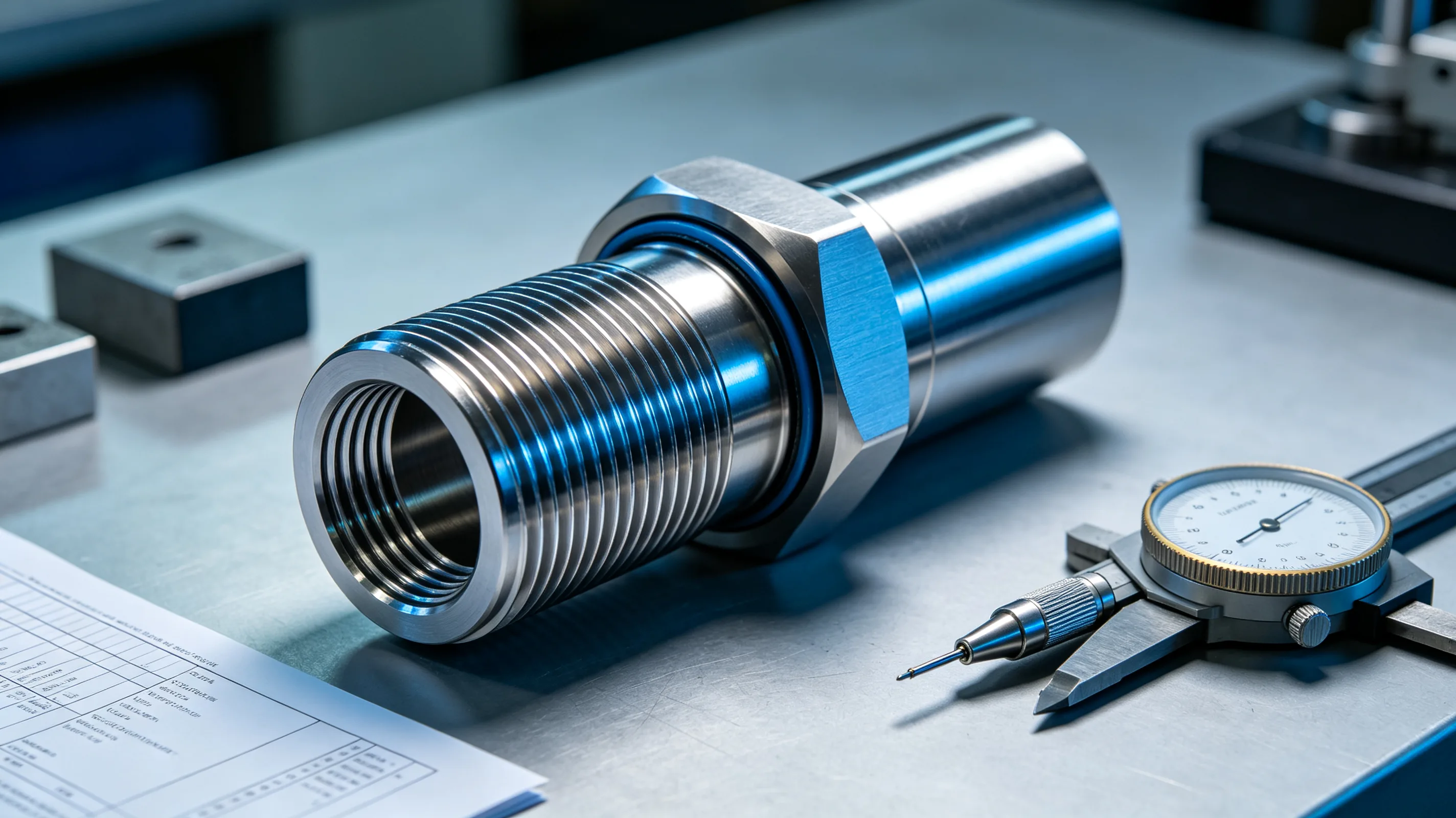
Titanium valve stems are critical components in subsea, aerospace, and industrial valve assemblies where corrosion resistance, high specific strength, and dimensional stability at elevated temperatures are required. A valve stem transmits the actuation force from the operator or actuator to the closure element — gate, ball, or plug — and must maintain sealing integrity through repeated operating cycles in environments that include seawater, hydrocarbon fluids, high-pressure steam, and chemical process streams. Machining a titanium valve stem to the required precision involves a multi-stage process that accounts for the material’s specific behaviour under cutting, the tolerance requirements for stem-to-packing and stem-to-closure interface fits, and the surface integrity needs for long service life in corrosive media. This article provides a detailed examination of how titanium valve stems are machined, from material selection through final inspection, for engineers and procurement teams specifying these components.
Executive summary
Titanium valve stem machining is a multi-stage precision process that transforms Ti-6Al-4V bar stock or forging into a component with concentricity tolerances of 0.025 mm TIR, surface finish requirements of Ra 0.4 µm or better on packing seal areas, and thread pitch diameter control within ±0.025 mm. The process sequence — rough turning, heat treatment (when specified), semi-finish turning, thread milling or turning, stem keyway or slot milling, and finish grinding or polishing — must be arranged to manage the residual stress relief that occurs as material is removed from the bar stock, which can cause dimensional shift of 0.05–0.10 mm on stems exceeding 500 mm in length. Material selection between Ti-6Al-4V Grade 5, Grade 23 ELI, and Ti-6Al-2Sn-4Zr-2Mo is determined by the operating temperature, corrosive media, and stem-to-stem seal galling resistance requirements. Quality verification involves dimensional inspection by CMM for geometric tolerances, surface finish measurement by contact profilometer, thread gauging by three-wire measurement, and NDT by dye penetrant inspection for surface defects.
Material selection for titanium valve stems
The material selection for a titanium valve stem is determined by the valve application, operating conditions, and stem function within the valve assembly.
Ti-6Al-4V Grade 5 for general industrial and subsea service
Ti-6Al-4V (Grade 5) is the most common titanium alloy specified for valve stems in industrial and subsea applications. It provides a yield strength of 830–900 MPa, good fatigue strength in seawater, and a stable passive film that resists pitting and crevice corrosion in chlorinated environments. Grade 5 is suitable for valve stems operating at temperatures up to 315 °C, making it applicable across the majority of industrial valve service conditions.
From a machining perspective, Grade 5 presents the standard titanium machining challenges — low thermal conductivity requiring coolant management, work-hardening tendency requiring consistent feed engagement, and springback requiring compensation in thread machining and keyway broaching operations. These challenges are well documented and can be managed with appropriate tooling, coolant, and process parameter selection by an experienced CNC machining supplier.
Ti-6Al-4V ELI Grade 23 for low-temperature and fracture-critical service
Ti-6Al-4V ELI (Grade 23) is specified for valve stems in cryogenic and HPHT subsea service where fracture toughness at low temperature is critical. The reduced interstitial element content (oxygen max 0.13 wt% versus 0.20 wt% for Grade 5) provides improved crack initiation resistance at subsea ambient temperatures of 4 °C and below. Grade 23 is also specified for valve stems in LNG service where operating temperatures can reach −196 °C.
Machining parameters for Grade 23 are similar to Grade 5, but the lower oxygen content produces slightly reduced work-hardening rates, allowing a marginal increase in feed rate during roughing passes. The difference is not large enough to change tooling or coolant strategy, but it can improve cycle time by 5–10 percent on long-stem components.
High-temperature titanium alloys for severe service
Ti-6Al-2Sn-4Zr-2Mo (Ti-6-2-4-2) is specified for valve stems in high-temperature service such as steam valves in power generation and hydrocarbon processing valves operating above 315 °C. This near-alpha alloy provides elevated temperature strength retention and creep resistance up to 540 °C. Ti-6-2-4-2 is significantly more difficult to machine than Grade 5 — the higher refractory alloy content increases abrasive wear on cutting tools, requiring AlTiN-coated carbide inserts at cutting speeds reduced to 10–20 m/min.
Machining process sequence for titanium valve stems
The machining process for a titanium valve stem follows a defined sequence that manages material stress relief, achieves concentricity between stem sections, and produces the surface finish required for packing seal and bearing interface areas.
Stage 1: Rough turning and stress relief
The machining process begins with rough turning of the titanium bar stock or forging to within 0.5–1.0 mm of finished dimensions. Rough turning is performed at cutting speeds of 15–25 m/min with depths of cut of 1.0–3.0 mm per pass, using CNMG or WNMG insert geometries with AlTiN coatings. Through-spindle coolant at 70–100 bar is essential to control the heat that softens the carbide cutting edge and accelerates flank wear.
The rough turning stage serves a dual purpose beyond material removal. The removal of approximately 20–30 percent of the bar stock diameter during roughing relieves residual stresses that are locked into the bar from the mill processing — rolling, forging, or extrusion. If these stresses are not relieved before finish machining, the stem will distort dimensionally as material is removed during later stages, causing the concentricity between the stem sections to shift beyond the tolerance band. A stress relief dwell period of 24–72 hours between rough turning and semi-finish turning is standard practice for valve stems exceeding 500 mm in length. For shorter stems, the stress relief occurs quickly enough that the dwell period can be reduced to 2–4 hours.
Where the valve stem specification requires heat treatment — solution treatment and ageing (STA) for Grade 5 stems requiring maximum strength — the rough-turned stem is sent to the heat treatment facility before semi-finish machining. Heat treatment introduces additional dimensional change as the microstructure transforms, so the stem must be returned to the machining cell for further processing after heat treatment is complete.
Stage 2: Semi-finish turning and feature roughing
After the stress relief dwell or heat treatment cycle, the stem is returned to the CNC lathe for semi-finish turning. This stage brings the stem diameters to within 0.2–0.3 mm of finished dimensions. Key features — the stem thread section, the packing seal section, the bearing journal section, and the stem-to-closure connection section — are rough-profiled at this stage.
Semi-finish turning uses the same cutting speeds and tooling as rough turning but with reduced depths of cut (0.3–0.5 mm per pass) to maintain dimensional accuracy and surface integrity. Cutting feed is maintained above 0.08 mm/rev to prevent rubbing that work-hardens the surface before the finish pass.
Stage 3: Finish turning and surface finishing
Finish turning of the titanium valve stem is performed at cutting speeds of 20–30 m/min with depths of cut of 0.1–0.2 mm per pass. Wiper geometry inserts at feed rates of 0.02–0.05 mm/rev produce surface finishes of Ra 0.4–0.8 µm on the stem diameters. For packing seal sections that require Ra 0.4 µm or better, a finish turning pass is followed by a polishing sequence using abrasive film or superfinishing stone.
Finish turning is performed in a single setup where possible — the stem is held in a precision chuck with tailstock support to maintain concentricity. For long stems exceeding 500 mm, a steady rest is positioned at the mid-point to dampen vibration and prevent deflection under cutting forces. The finish turning sequence proceeds from the tailstock end toward the chuck end to maintain consistent tool engagement.
Stage 4: Thread machining
Valve stem threads — typically ACME or stub ACME for linear motion valves, UN or metric threads for component connections — are machined after the stem diameters are finished. Thread milling is the preferred method for titanium valve stems because it produces consistent thread form and avoids the thread tearing risk associated with thread turning on titanium.
Thread milling of ACME threads on titanium valve stems uses single-point thread mills or full-profile thread mills depending on the thread size. For stem threads up to 75 mm diameter, full-profile thread mills produce consistent thread form in a single helical interpolation pass. For larger threads, single-point thread mills with multiple passes are used. Cutting speed for thread milling is 20–30 m/min with feed per tooth of 0.02–0.05 mm. Thread milling coolant is supplied through the tool holder at minimum 50 bar pressure to flush chips from the thread profile.
Thread turning, where specified, requires insert geometries designed for titanium — sharp edge with AlTiN coating — and feed rates of 0.05–0.10 mm/rev. Multiple thread turning passes (8–12 passes for a typical ACME thread) are used to distribute cutting engagement and heat generation across the thread profile.
Stage 5: Keyway and cross-hole machining
Valve stems typically include a keyway or slot at the actuator connection end and a cross-hole or slot at the closure connection end. These features are machined after the stem diameters and threads are complete, to avoid stress relief effects that could affect concentricity.
Keyway broaching on titanium valve stems requires broach tool geometry designed for titanium — high positive rake angle, sharp cutting edge, and AlTiN coating. Broaching speed is maintained at 3–6 m/min with flood coolant directed into the broach flutes. Chip accumulation in broach flutes is the primary cause of broach failure on titanium; the broach must be cleaned after each pass.
Where wire EDM is used for keyway or slot machining instead of broaching, the stem can be machined with the keyway in a single pass with no tool wear concern. Wire EDM produces a surface finish of Ra 1.6–2.5 µm in the keyway, which is acceptable for actuator interface fits. If the keyway surface finish requirement is Ra 1.6 µm or better, a secondary EDM skim cut is required.
Cross-hole drilling for stem-to-closure connection pins is performed using solid carbide drills at cutting speeds of 10–15 m/min with peck drilling cycles to break and evacuate chips. Pilot drilling at 50–60 percent of finished hole diameter reduces thrust force and prevents drill wander on the curved stem surface.
Precision requirements and dimensional verification
Titanium valve stems are machined to tolerance specifications that ensure correct fit with the valve body packing, bearing supports, and closure element.
Concentricity and runout tolerances
The concentricity between the valve stem packing section, bearing journal section, and closure connection section is specified at 0.025 mm TIR or better for precision valves. This concentricity requirement ensures that the stem rotates or translates without eccentric motion that would accelerate packing wear and increase actuation torque.
Concentricity verification is performed by mounting the finished stem between precision centres and measuring runout at each section using a dial indicator or electronic gauge. The measurement is performed at controlled temperature (20 ±1 °C) after the stem has stabilised for a minimum of 2 hours.
Diameter tolerances and fits
Stem diameter tolerances follow ISO IT6 to IT7 grade, corresponding to ±0.006 mm for diameters under 18 mm, ±0.009 mm for diameters 18–30 mm, and ±0.012 mm for diameters 30–50 mm. Packing seal section diameters are typically specified at IT6 grade to control the clearance between the stem and packing rings, preventing leakage without causing excessive friction.
Diameter verification is performed by micrometre measurement at defined positions along each stem section. In-process diameter gauging using electronic bore plugs or air gauging provides real-time dimensional feedback during the finish turning passes.
Surface finish specifications
Surface finish requirements for titanium valve stems vary by functional section.
Packing seal section: Ra 0.2–0.4 µm. This surface finish ensures that the stem contacts the packing rings with minimal friction while maintaining a sealing interface. Achieving this finish on titanium requires a finish turning pass with wiper insert (feed ≤0.03 mm/rev) followed by abrasive film polishing with 400–600 grit silicon carbide.
Bearing journal section: Ra 0.4–0.8 µm. This surface finish is sufficient for bearing contact surfaces where the stem rotates or translates through sleeve bearings or bushings.
Thread section: Ra 0.8–1.6 µm on thread flanks. Thread surface finish is controlled through thread milling feed rate selection and, where thread turning is used, through wiper geometry inserts.
Non-sealing external surfaces: Ra 1.6–3.2 µm. These surfaces require no special finishing beyond the semi-finish turning pass.
Quality assurance and testing
Final quality assurance for machined titanium valve stems includes dimensional inspection, surface finish measurement, thread gauging, and non-destructive testing.
Dimensional inspection
The finished valve stem undergoes CMM inspection that verifies every dimension on the component drawing. The inspection report includes diameter measurements at each section, concentricity and runout measurements, length measurements, thread pitch diameter and form verification, and keyway position and width measurements. Measurement results are compared against tolerance limits with pass/fail status for each dimension.
Surface finish verification
Surface finish is measured at the packing seal section, bearing journal section, and thread flanks using a contact profilometer with a 2 µm or 5 µm stylus. Measurement parameters include Ra, Rz, and Rmax. The measurement traverse length is specified to include at least five roughness sampling lengths to provide statistically representative results.
Thread gauging
Thread pitch diameter is verified by three-wire measurement using calibrated wires of the diameter specified for the thread pitch. The measurement is corrected for thread form deviation where required by the thread standard. Go/No-Go thread plug gauges are used for connection threads on the stem ends.
Non-destructive testing
Dye penetrant inspection per ASTM E1417 is performed on all machined titanium valve stems to detect surface cracks, laps, and other defects introduced during the machining process. The inspection covers the entire machined surface, with particular attention to thread roots, keyway corners, and cross-hole intersections where stress concentration and machining-induced defects are most likely to occur. For valve stems specified for critical service, ultrasonic inspection per ASTM E2375 is performed on the bar stock or forging before machining, and again on the finished stem where wall thickness permits.