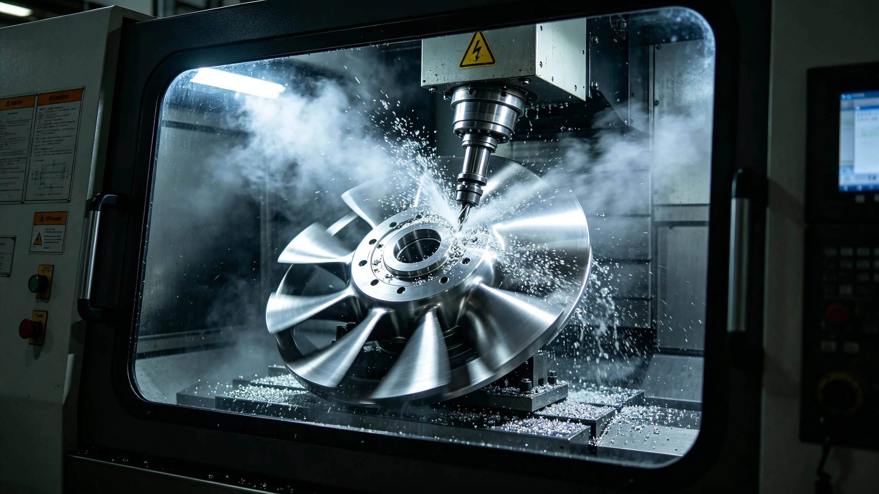
Five-axis machining offers advantages for titanium that go beyond the ability to produce complex geometries. The ability to orient the tool relative to the workpiece changes the cutting mechanics in ways that directly address several of the fundamental challenges of titanium machining — thermal concentration, tool engagement control, and vibration management. But realizing these advantages requires programming strategies that differ from what works for 3-axis machining and from what works for 5-axis machining of aluminum or steel. For an overview of how these strategies are applied on production components, see our 5-axis titanium machining services.
- How 5-axis machining changes the cutting mechanics for titanium
- Tool orientation principles for rigid cutting conditions
- Chip load management in complex toolpaths
- Thermal distribution across multi-axis moves
- Programming approaches for 5-axis titanium roughing and finishing
How 5-axis machining changes the cutting mechanics for titanium
In 3-axis machining, the tool axis is fixed, and the cutting conditions are determined entirely by the toolpath in the X-Y plane and the depth in Z. The tool engagement angle varies with the geometry of the part, and in internal corners the engagement can increase sharply, generating a spike in cutting forces and temperature. For titanium, these engagement spikes are where tool failure occurs and where surface finish degrades.
Five-axis machining allows the tool to be tilted so that the cutting edge engages the material at a more favorable angle. Instead of cutting with the bottom of the tool, which creates a zero-surface-speed point at the center of the tool, the tool is tilted so that cutting occurs along the side of the tool where the surface speed is consistent. This changes the chip formation mechanism from one dominated by rubbing and smearing at the tool center to one dominated by clean shearing along the cutting edge.
The ability to tilt the tool also changes how the cutting forces are directed. In 3-axis machining, the cutting forces are primarily radial, pushing the tool away from the cut and deflecting the workpiece. In 5-axis machining with appropriate tool tilt, a portion of the cutting force is directed axially into the spindle, which is the stiffest direction of the machine tool. The reduced radial load means less deflection of both the tool and the workpiece, which is particularly valuable for thin-wall titanium components where deflection is a primary limitation.
Tool engagement control is fundamentally different in 5-axis machining. In 3-axis trochoidal milling, the toolpath is designed to maintain a constant radial engagement by moving the tool in a curved path. In 5-axis machining, the engagement can be controlled not only by the toolpath geometry but also by the tool orientation. A tilted tool with a small engagement angle removes material with a thin chip that is easier to cool and evacuate, at the cost of requiring more passes to cover the same area.
Tool orientation principles for rigid cutting conditions
The primary rule for 5-axis tool orientation in titanium is to avoid cutting with the center of the tool. The center of a rotating end mill has zero surface speed, and when this region contacts the workpiece, it rubs rather than cuts. The rubbing generates heat without material removal, and in titanium, this heat accelerates tool wear and can produce localized surface damage. A tilt angle of 3 to 5 degrees from the surface normal is typically sufficient to move the cutting zone away from the tool center while maintaining effective material removal. This principle is applied in 5-axis CNC machining centers configured specifically for titanium aerospace work.
The lead angle — the angle between the tool axis and the surface normal in the direction of travel — determines how the cutting forces are distributed. A positive lead angle of 5 to 10 degrees directs the cutting forces axially into the spindle and produces a clean shearing action. A negative lead angle directs forces radially and increases the risk of deflection and chatter. For titanium finishing operations, a positive lead angle is strongly preferred.
The tilt angle — the angle perpendicular to the direction of travel — determines the location of the cutting zone on the tool. A tilt away from the surface being machined reduces the effective radial engagement and produces a thinner chip. This is useful for finishing passes where surface finish quality is the priority. A tilt toward the surface increases engagement and material removal rate but also increases cutting forces and heat generation.
For 5-axis roughing of titanium, the tool orientation should prioritize chip thinning and heat management. A tilt angle of 3 to 5 degrees with a lead angle of 5 to 8 degrees provides a balance between material removal rate and thermal control. For finishing, the tilt angle can be increased to 5 to 10 degrees to produce a thinner chip and a better surface finish, with the lead angle reduced to 3 to 5 degrees to maintain stability.
Tool orientation should not be static throughout the toolpath. In complex 5-axis toolpaths where the tool moves around a feature, the relationship between the tool axis and the surface changes continuously. The CAM system should be configured to maintain a consistent effective rake angle and clearance angle as the tool moves, rather than holding a fixed tool axis orientation relative to the machine coordinate system.
Chip load management in complex toolpaths
Chip load management in 5-axis titanium machining is more complex than in 3-axis because the chip thickness varies not only with the toolpath geometry but also with the tool orientation. A tool that is tilted relative to the surface produces a chip that is thinner than the feed per tooth would suggest, and the thinning factor changes with the tilt angle.
The effective chip thickness in 5-axis machining can be calculated from the feed per tooth, the tool orientation angles, and the surface curvature. In practice, the chip thinning effect means that the feed rate must be adjusted upward to maintain the design chip load when the tool is tilted. A tool tilted at 10 degrees may require a 20 to 30 percent higher feed rate to achieve the same chip thickness as a tool cutting normal to the surface.
For 5-axis roughing of titanium, the chip load should be maintained in the range of 0.04 to 0.08 mm per tooth, depending on the tool diameter and the machine rigidity. The lower end of this range is appropriate for small tools below 12 mm diameter or for operations with long tool overhangs. The upper end is for large tools in rigid setups. Exceeding 0.10 mm per tooth in titanium 5-axis roughing increases the risk of tool failure from excessive cutting forces.
For 5-axis finishing, the chip load should be reduced to 0.02 to 0.05 mm per tooth. The lower chip load produces a better surface finish and reduces the cutting forces that can cause deflection in thin-wall features. The trade-off is that the effective material removal rate is lower, and finishing a large surface requires more passes. Given the cost of rework on titanium aerospace components, the additional finishing time is usually justified.
Constant chip load toolpaths that adjust the feed rate to maintain a consistent chip thickness throughout the toolpath are particularly valuable for 5-axis titanium machining. These toolpaths account for variations in radial engagement, axial engagement, and tool orientation, and they adjust the feed rate in real time to keep the chip load within the target range. The result is more consistent tool wear and surface finish across the entire machined surface.
Thermal distribution across multi-axis moves
In 3-axis machining of titanium, the heat generated at the cutting zone is concentrated in a small area, and the thermal load on the tool is determined primarily by the cutting speed and the material removal rate. In 5-axis machining, the continuous movement of the tool relative to the workpiece distributes the thermal load over a larger area of both the tool and the workpiece.
The thermal benefit of 5-axis machining is that the tool does not dwell in one orientation long enough for the heat to accumulate to the same degree as in 3-axis machining. As the tool rotates around a feature, the cutting zone moves along the tool edge, and the hottest point on the tool changes continuously. This distributed thermal loading can reduce the peak temperature at any single point on the tool by 50 to 100°C compared to a stationary orientation at the same cutting speed.
The thermal distribution effect is most pronounced in 5-axis contouring operations where the tool follows a complex path around a feature. The tool engagement varies as the tool moves around corners and over curved surfaces, and the heat input at any given point is intermittent rather than continuous. This allows the tool to cool between engagement periods, reducing the average temperature and extending tool life.
However, the thermal distribution benefit depends on the toolpath strategy. Toolpaths that produce long, continuous cuts with the same tool orientation — even in 5-axis mode — do not provide the same thermal benefit as toolpaths that vary the orientation continuously. For titanium, the programming approach should favor toolpaths that distribute the cut over a larger portion of the tool geometry, even if this requires more passes, rather than concentrating the cut on a small section of the tool.
The intermittent cooling that occurs during orientation changes also benefits the workpiece surface. Surfaces that are machined with continuous 5-axis toolpaths show less thermal damage than surfaces machined with 3-axis toolpaths at equivalent material removal rates, because the workpiece surface has time to cool between passes of the tool as it moves around the feature.
Programming approaches for 5-axis titanium roughing and finishing
For roughing complex titanium components on a 5-axis machine, the programming strategy should prioritize stable cutting conditions over maximum material removal rate. In titanium, the limiting factor in roughing is rarely the machine’s power or torque — it is the tool’s ability to survive the thermal and mechanical loads long enough to complete the operation.
Trochoidal roughing toolpaths that maintain a constant radial engagement are the standard approach for 5-axis titanium roughing. The toolpath keeps the tool in constant motion, avoiding the engagement spikes that occur at corners in conventional toolpaths. The radial engagement should be set at 20 to 30 percent of the tool diameter for titanium roughing, which is lower than the 40 to 50 percent typical for steel but necessary to manage the thermal load.
For finishing, the programming strategy shifts to prioritizing surface quality and dimensional accuracy. The toolpath should maintain a consistent stepover and a consistent tool orientation relative to the surface. Variations in stepover produce visible surface banding on titanium components, and variations in tool orientation change the surface finish characteristics across the part.
Rest machining — where the CAM system identifies areas that were not reached by the previous larger tool and generates dedicated toolpaths to machine those areas — is particularly important for 5-axis titanium finishing. Without rest machining, the finishing tool may encounter uncut material in internal corners or narrow features, and the sudden increase in engagement can cause tool failure or surface damage.
Simultaneous 5-axis finishing, where all five axes move simultaneously to maintain optimal tool orientation, produces the best surface quality for complex titanium surfaces. The tool maintains a consistent orientation relative to the surface normal, and the cutting conditions remain stable throughout the toolpath. The programming complexity is higher than for 3+2 machining (where the tool axis is positioned and locked), but the improvement in surface consistency justifies the additional programming time for critical aerospace surfaces.
3+2 machining — positioning the tool axis at a fixed orientation and machining with only three axes — is a practical alternative for less critical surfaces and for roughing operations where surface quality is not the primary concern. The programming is simpler, and the machine motion is faster because fewer axes are moving simultaneously. For titanium, 3+2 machining is effective for roughing and for finishing non-contoured surfaces where the tool orientation does not need to change.
Table 1: 5-axis parameter guidelines for Ti-6Al-4V
| Operation | Tilt angle | Lead angle | Chip load (mm/tooth) | Radial engagement | Surface speed (m/min) |
|---|---|---|---|---|---|
| Roughing, 3+2 | 3–° | 5–° | 0.04–0.08 | 20–0% | 40–0 |
| Roughing, simultaneous | 3–° | 5–° | 0.04–0.06 | 15–5% | 40–0 |
| Semi-finishing | 5–° | 3–° | 0.03–0.06 | 10–0% | 50–0 |
| Finishing, 3+2 | 5–0° | 3–° | 0.02–0.05 | 5–5% | 50–0 |
| Finishing, simultaneous | 5–0° | 3–° | 0.02–0.04 | 3–0% | 50–5 |
Table 2: 5-axis vs 3-axis comparison for titanium
| Factor | 3-axis | 5-axis | Why it matters for titanium |
|---|---|---|---|
| Tool center cutting | Required | Avoided via tilt | Eliminates rubbing and smearing |
| Cutting force direction | Radial | Partially axial | Axial loading uses machine stiffness |
| Thermal distribution | Concentrated | Distributed | Reduces peak tool temperature |
| Corner engagement | Spikes | Managed via tilt | Prevents engagement-induced tool failure |
| Thin-wall capability | Limited | Improved | Lower radial forces reduce deflection |
| Programming complexity | Lower | Higher | Required for complex aerospace parts |