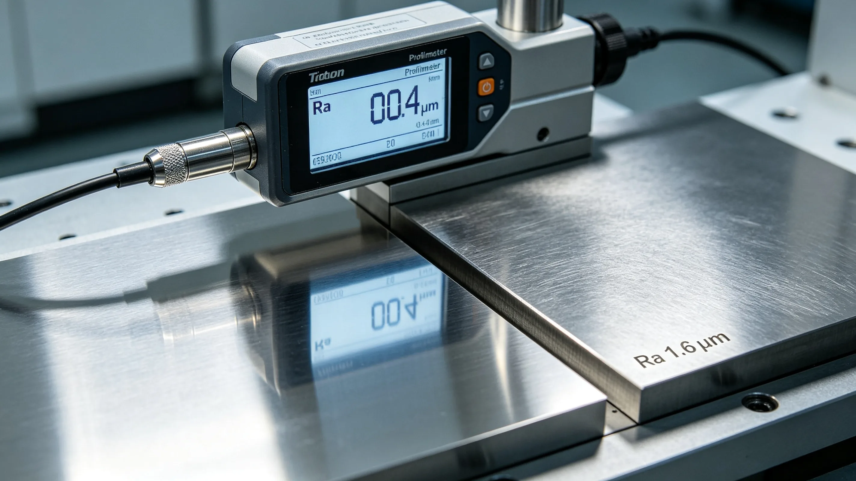
Surface finish in titanium machining is not a simple function of feed rate and tool radius. The material’s tendency to form a built-up edge, the elastic springback that alters the effective tool engagement, and the vibration response of thin-wall features all influence the surface that the tool leaves behind. Achieving consistent surface finish at Ra 0.4 μm or better requires understanding how these factors interact and how they change over the life of the cutting tool.
- What determines surface finish in titanium machining
- Tool geometry and its effect on surface generation
- Cutting parameters for specific finish targets
- Surface integrity versus surface roughness
- Post-machining surface enhancement options
What determines surface finish in titanium machining
In conventional machining theory, surface roughness is calculated from feed rate and tool nose radius using a straightforward geometric relationship. In titanium, this relationship holds only under ideal conditions — a sharp tool, stable cutting conditions, and no built-up edge formation. In practice, all three of these conditions are difficult to maintain simultaneously over a production run, particularly when tool wear is actively changing the cutting edge geometry.
Built-up edge is the most common cause of surface finish degradation in titanium. At the temperatures and pressures present at the cutting interface, titanium particles weld to the tool edge, forming an unstable protrusion that changes the effective cutting geometry. As the built-up edge grows and periodically breaks away, it leaves an irregular surface pattern that can be two to three times rougher than the theoretical value predicted by the feed-and-radius calculation. The built-up edge also creates localized tearing on the machined surface, producing a characteristic smeared appearance that is visible under moderate magnification.
The onset of built-up edge depends on cutting speed. At very low speeds, below approximately 20 m/min, the temperature at the cutting interface is low enough that adhesion dominates and built-up edge is severe. As speed increases above 40 m/min, the temperature rises and the built-up edge becomes less stable, producing an intermittent pattern. Above 60 m/min, the temperature is high enough that the built-up edge largely disappears, but by this point tool wear from diffusion is accelerating rapidly. The window between built-up edge and excessive tool wear — roughly 45 to 55 m/min for uncoated carbide — is where the best surface finish is typically achieved, but it is a narrow range and shifts as the tool wears.
Vibration is the second most common cause of surface finish problems. In titanium, the combination of high cutting forces and low elastic modulus makes the system prone to chatter, particularly when machining thin-wall features or using long tool overhangs. Vibration marks on the surface are distinct from built-up edge marks — they appear as regular, evenly spaced ridges rather than irregular tearing. The spacing of the ridges corresponds to the vibration frequency, and the depth of the ridges depends on the vibration amplitude. A system that is producing a surface finish of Ra 0.4 μm under stable conditions can produce Ra 1.0 μm or worse when vibration is present, even with identical feed and speed settings.
Tool geometry and its effect on surface generation
Tool nose radius has the most direct influence on theoretical surface finish. A larger nose radius produces a smoother surface at the same feed rate because the scallop height between successive feed marks is lower. But in titanium, larger nose radii also increase cutting forces, which can exacerbate deflection and vibration problems. A tool with a 0.8 mm nose radius that produces excellent surface finish on a rigid, thick-walled part may produce unacceptable chatter marks on a thin-wall component because the higher cutting forces excite vibration.
The practical approach is to select the largest nose radius that the part geometry and stability allow, rather than targeting a specific radius from surface finish calculations alone. For thin-wall titanium finishing, a 0.4 mm radius is often a better starting point than 0.8 mm because the lower cutting forces allow more stable cutting, and the surface finish difference can be compensated by reducing the feed rate.
Edge preparation matters for surface finish in a way that is specific to titanium. A sharp cutting edge produces the cleanest surface because it shears the material cleanly with minimal deformation. But sharp edges are also more susceptible to microchipping in titanium, particularly when cutting through the work-hardened surface layer. A slightly honed edge –0.02 to 0.05 mm radius — is more stable and produces more consistent surface finish over the life of the tool, even though the initial surface may be slightly rougher than a sharp edge.
Tool runout in multi-insert tools or multi-flute cutters creates a periodic surface pattern. When one flute is slightly longer than the others, it takes a heavier cut and leaves a deeper feed mark, while the shorter flutes take lighter cuts. The resulting surface shows a pattern where every nth feed mark is deeper than the intervening marks. In titanium, where the finish tolerance is tight, runout should be held below 0.01 mm for finishing operations. This often requires the use of hydraulic or shrink-fit tool holders rather than mechanical collets, which typically cannot maintain this level of concentricity over repeated tool changes.
Cutting parameters for specific finish targets
For a target of Ra 0.4 μm in titanium finishing, the feed rate per revolution should typically be in the range of 0.05 to 0.10 mm per revolution when using a 0.4 mm nose radius tool. Reducing feed rate below 0.05 mm provides diminishing returns because the minimum achievable roughness is limited by built-up edge and vibration rather than the geometric scallop height. Increasing feed rate above 0.10 mm increases productivity but pushes the theoretical roughness above Ra 0.4 μm, requiring a larger nose radius to compensate.
Cutting depth in finishing passes affects surface finish through its influence on cutting forces and vibration. A depth of cut between 0.1 and 0.3 mm is typical for titanium finishing. Depths below 0.1 mm can be problematic because the tool may rub rather than cut, particularly if the work-hardened surface layer from roughing is harder than the bulk material. The rubbing action generates additional heat and can smear the surface rather than shearing it cleanly, producing a poor finish. Depths above 0.3 mm increase cutting forces and may push thin-wall features past their stable deflection range.
Coolant pressure and direction have a direct effect on surface finish that is often underestimated. At coolant pressures below 30 bar, the coolant stream may not reach the cutting edge effectively, particularly in deep pockets or internal features where the tool is at an angle to the coolant nozzle. The result is localized hot spots that promote built-up edge formation and inconsistent surface quality. Through-spindle coolant delivery at 50 bar or higher ensures that the cutting edge is consistently lubricated and cooled, which stabilizes the built-up edge behavior and produces more consistent surface finish across the part.
The condition of the coolant itself matters for finish consistency. Coolant that has degraded — either through concentration drift or contamination with tramp oil — loses its lubricity, and the increased friction at the tool-chip interface raises local temperatures. Shops that monitor coolant concentration daily and maintain it within the recommended range report fewer surface finish surprises than those that rely on periodic top-offs.
Surface integrity versus surface roughness
Surface roughness measured as Ra or Rz describes only the geometric texture of the surface. Surface integrity describes the condition of the material beneath that texture — the residual stress state, the microstructural condition, and the presence of cracks or defects. Two surfaces with identical Ra values can have dramatically different performance characteristics if their surface integrity differs.
In titanium components subject to fatigue loading, surface integrity matters more than surface roughness. A surface that is rough but has a clean, undeformed subsurface layer will often outperform a smooth surface that has a deep work-hardened layer with microcracks. This is because fatigue cracks initiate at microstructural defects in the subsurface layer, not at surface feed marks. A feed mark that is 0.4 μm deep but has clean material beneath it is less likely to initiate a fatigue crack than a smooth surface that has 50 μm of deformed, cracked subsurface material.
Residual stress is a component of surface integrity that is often specified in aerospace surface finish requirements. Compressive residual stress at the surface improves fatigue life by opposing crack opening. Tensile residual stress reduces fatigue life by assisting crack propagation. The cutting parameters that produce the best surface roughness — low feeds, sharp tools, moderate speeds — also tend to produce compressive residual stress because they minimize thermal damage. But the relationship is not guaranteed, and changes in coolant effectiveness or tool wear state can shift the residual stress from compressive to tensile without changing the surface roughness.
For medical implant components, surface integrity requirements extend to the absence of embedded contaminants. Titanium is bio-compatible, but surface contaminants such as carbide particles from tool wear or iron from coolant residue can compromise bio-compatibility. Medical surface finish specifications often include not only roughness limits but also requirements for surface cleanliness and freedom from embedded particles. These requirements are typically verified through microscopic inspection at magnifications of 50x to 200x, which reveals contaminants that would not be detected by profilometer measurement alone. Surface finish specifications for different applications are covered in more detail in the design engineering resources.
Post-machining surface enhancement options
For applications where the as-machined surface finish does not meet requirements, several post-machining surface treatment processes can improve surface condition. The choice of process depends on whether the goal is to reduce roughness, improve surface integrity, or both.
Mechanical polishing reduces surface roughness by abrasively removing the feed mark peaks. In titanium, polishing must be done with care because the abrasives can embed in the soft titanium surface. Silicon carbide or aluminum oxide abrasives at progressively finer grit sizes, from 400 to 1200 grit, are typical. The polishing process removes material, so dimensional changes must be accounted for in the preceding machining operations. For tight-tolerance features, the machining allowance for polishing is typically 0.01 to 0.02 mm per surface.
Vibratory finishing and tumbling are used for批量 processing of smaller titanium components. The process reduces surface roughness and can also impart compressive residual stress through peening action. The effectiveness depends on the media type, the cycle time, and the geometry of the parts. For complex geometries with internal features, the media may not reach all surfaces uniformly, and selective manual polishing of critical areas may be required.
Shot peening is used specifically to improve surface integrity by inducing compressive residual stress. The peening process bombards the surface with small spherical media at high velocity, creating a layer of compressive stress that can extend 0.1 to 0.3 mm below the surface. Shot peening does not significantly reduce surface roughness — in fact, it can increase it — but it improves fatigue performance substantially. For aerospace titanium components, shot peening is often specified for highly loaded features regardless of the as-machined surface finish.
Chemical etching and electropolishing remove a uniform layer of material from the surface, eliminating the work-hardened subsurface layer and leaving a clean, stress-free surface. These processes are effective for improving surface integrity but have limited effect on roughness, as they tend to follow the existing surface contour. Electropolishing can produce a bright, reflective surface on titanium, but the roughness is determined by the starting condition of the surface before polishing.
Table 1: Surface finish capability by operation type (Ti-6Al-4V)
| Operation | Typical Ra range (μm) | Limiting factor | Primary control |
|---|---|---|---|
| Roughing | 1.6–0.2 | Tool wear, vibration | Depth of cut, rigidity |
| Semi-finishing | 0.8–0.6 | Built-up edge | Speed selection |
| Finishing, standard | 0.4–0.8 | Nose radius, feed | Tool geometry selection |
| Finishing, precision | 0.2–0.4 | Vibration, built-up edge | Coolant, tool condition |
| Polishing (post-machining) | 0.05–0.2 | Abrasive selection | Grit progression |
Table 2: Parameter effects on surface finish in titanium
| Parameter | Typical range for Ra –0.4 μm | Effect on surface | Trade-off |
|---|---|---|---|
| Feed rate | 0.05–0.10 mm/rev | Directly sets scallop height | Lower feed increases cycle time |
| Nose radius | 0.4–0.8 mm | Larger radius = smoother surface | Larger radius increases forces |
| Cutting speed | 45–5 m/min | Avoids BUE and rapid wear zones | Narrow optimal window |
| Depth of cut | 0.1–0.3 mm | Below 0.1 = rubbing risk | Deeper cuts increase deflection |
| Coolant pressure | 50+ bar | Stabilizes BUE, controls temperature | Higher pressure requires pump capacity |
To compare achievable Ra values across machining operations and post-processing methods, use our surface roughness comparator.