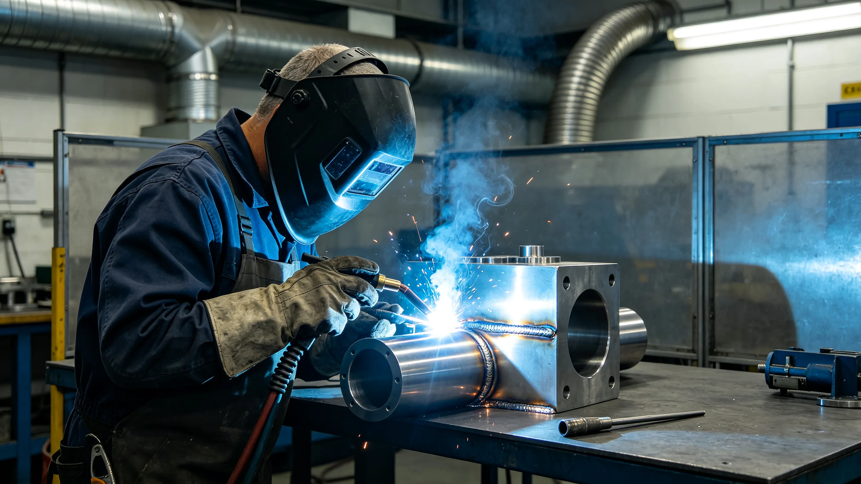
Welding titanium components that have been CNC machined requires coordination between the machining and welding processes that is often underestimated. The machined surfaces must be protected from contamination during welding, the weld zones must be accounted for in the machining sequence, and the distortion from welding must be managed to maintain the dimensional accuracy achieved in machining. The interaction between welding heat input and pre-existing machined features is related to the deformation mechanisms discussed in the context of thermal expansion and residual stress redistribution. These interfaces are managed end-to-end in our titanium welding and assembly services.
Weld joint design for machined titanium components
Weld joint design for titanium components that are machined before welding should account for the weld zone geometry and the effect of welding on adjacent machined surfaces. The joint design should provide sufficient material in the weld zone to accommodate the weld reinforcement without requiring post-weld machining of the weld area if the design allows.
For butt joints in titanium sheet or plate, a square butt joint with a controlled gap of 1.0 to 1.5 mm is typical for material thicknesses up to 3 mm. For thicker sections, a single-V or double-V joint preparation with a 60 to 70 degree included angle is used. The joint preparation is typically machined rather than ground, because grinding can embed abrasive particles in the titanium surface.
The weld joint location should be selected to minimize the effect of weld distortion on critical machined surfaces. Welds near thin-wall features or tight-tolerance surfaces can distort those features during cooling. The welding sequence should be planned to balance the thermal input and control distortion.
Inert gas shielding requirements
Titanium welding requires inert gas shielding to protect the molten weld pool and the heat-affected zone from atmospheric contamination. The shielding gas — typically argon or argon-helium mixtures — is applied to the weld zone through the torch nozzle, a trailing shield that follows the weld, and backup shielding that protects the underside of the weld.
The shielding effectiveness is verified by the color of the weld and heat-affected zone after welding. A bright silver color indicates adequate shielding. Light straw or gold indicates slight contamination that is acceptable for some applications. Blue or purple indicates significant contamination, and gray or white indicates severe contamination that requires the weld to be removed and rewelded.
The shielding gas flow rate depends on the welding current, travel speed, and joint geometry. Typical flow rates are 10 to 20 liters per minute through the torch, with additional flow through the trailing and backup shields. The gas delivery system should be tested for leaks before welding, and the gas purity should be verified as 99.995 percent or higher.
Distortion control and post-weld machining
Welding distortion in titanium assemblies can be significant because the material’s low thermal conductivity creates steep thermal gradients that drive distortion. The distortion pattern depends on the weld joint geometry, the welding sequence, and the restraint provided by the assembly.
Pre-bending or pre-setting the components before welding can compensate for predictable distortion patterns. The amount of pre-set is determined from experience or from welding trials on representative test pieces. For complex assemblies with multiple welds, the welding sequence should be planned to balance the thermal input across the assembly.
Post-weld stress relief is performed at 500 to 600°C for Ti-6Al-4V assemblies to reduce residual stresses from welding. The stress relief cycle is performed in a vacuum furnace or under inert gas shielding to prevent alpha case formation. After stress relief, the assembly is typically finish-machined to restore dimensional accuracy.
The machining allowance for post-weld machining should be established during process planning. Welded assemblies typically require 0.5 to 1.0 mm of stock on machined surfaces that will be finished after welding, to allow for distortion correction and weld cleanup.
Surface protection during welding
Machined surfaces near the weld zone must be protected from weld spatter, heat damage, and contamination. Protective coatings or shielding blankets are applied to machined surfaces within 50 to 100 mm of the weld joint. The protective material must not contain compounds that could contaminate the titanium surface at elevated temperatures.
Welding sequence planning should prioritize welds that are near critical machined surfaces. Those welds should be performed first, so that any distortion or surface damage can be addressed in the subsequent machining operations. Welds near non-critical surfaces can be performed later in the sequence.
Table 1: Titanium welding parameters for machined assemblies
| Material thickness | Weld joint | Shielding gas | Pre-weld preparation | Post-weld treatment |
|---|---|---|---|---|
| 1.0–0.0 mm | Square butt, 1.0–0.5 mm gap | Argon, 15–0 L/min | Chemical clean, solvent degrease | Stress relief if required |
| 3.0–0.0 mm | Single-V, 60° included angle | Argon, 20–5 L/min | Machine joint prep, chemical clean | Stress relief required |
| 6.0–2.0 mm | Double-V, 60° included angle | Argon-He mix, 25–0 L/min | Machine joint prep, chemical clean | Stress relief required, NDE after |
For welded titanium assemblies that require coordinated machining and welding, submit your RFQ and our engineers will plan the joint design, shielding, and post-weld machining sequence.