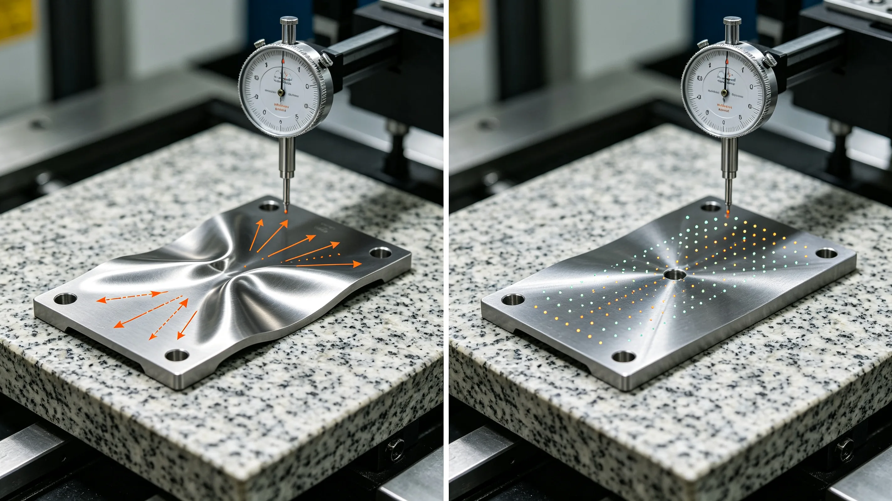
Dimensional deformation in titanium machining is not a single problem with a single cause. Thermal expansion from localized heating, elastic springback from low modulus, and residual stress redistribution from material removal all contribute to parts ending up outside tolerance. The challenge is that these mechanisms interact — a part that thermally expands during roughing may spring back differently during finishing because the residual stress state has changed. This article breaks down each deformation driver and what can be done to maintain dimensional control.
- Thermal expansion and contraction cycles
- Elastic springback and residual stress redistribution
- Thin-wall deformation patterns
- Fixturing and clamping strategies
- Toolpath strategies that minimize deformation
Thermal expansion and contraction cycles
Titanium’s low thermal diffusivity does more than accelerate tool wear — it creates a thermal expansion problem that is often underestimated in process planning. When a cutting tool passes over a local area, the heat generated does not dissipate quickly into the surrounding material. The heated zone expands locally while the surrounding cooler material constrains it. After the tool passes, the heated zone cools and contracts, but because the surrounding material has not changed temperature, the contraction creates a localized tensile stress state.
In thin-wall sections, this thermal cycling can produce visible distortion. A wall that is machined on one side will expand locally during the cut, then contract after the tool passes, pulling the wall slightly toward the machined side. When the opposite side is machined in a subsequent operation, the same cycle occurs in the opposite direction. The net result can be a wall that is thinner than intended at the center and thicker at the edges, or one that has a permanent bow.
The magnitude of thermal deformation depends on the temperature rise at the cutting zone and the constraint provided by the surrounding material. In heavy roughing operations where the temperature rise can exceed 300°C at the tool interface, the thermal expansion in the cutting zone can reach several microns per millimeter of engagement. For a 50 mm deep pocket wall, a 300°C local temperature rise produces approximately 0.25 mm of thermal expansion — enough to affect tight tolerances on the following pass.
One approach that helps is to allow the workpiece to return to thermal equilibrium between roughing and finishing. In production environments where parts are roughed and finished in the same setup, the machine spindle and coolant system are also generating heat, and the thermal state of both the workpiece and the machine is continuously changing. Allowing a stabilization period of 15 to 30 minutes between roughing and finishing, or scheduling roughing and finishing on separate shifts, can reduce thermal distortion significantly.
Elastic springback and residual stress redistribution
The elastic springback described in the context of work hardening also affects part-level deformation. Titanium’s modulus of 105 to 115 GPa means that under cutting forces, the part deflects elastically during machining. When the tool passes and the force is removed, the material springs back. In simple geometries, this springback is predictable and can be compensated in the CAM program. In complex geometries with varying section thicknesses, the springback varies across the part, and a single compensation value cannot address all locations.
Residual stress redistribution is a slower-acting but potentially more damaging deformation mechanism. Titanium mill products — plate, bar, and forgings — contain residual stresses from the manufacturing process. These stresses are in equilibrium within the material. When material is removed during machining, the equilibrium is disturbed, and the part deforms to reach a new stress balance. The deformation can be immediate or can occur over hours or days after machining.
The risk of residual stress redistribution is highest in parts with high material removal ratios — components where 80 percent or more of the starting stock is machined away. Aerospace structural parts machined from thick plate are typical examples. The stresses locked in the original plate are not uniformly distributed through the thickness, and as material is removed from one side, the part can bow or twist significantly. In extreme cases, the deformation can be several millimeters on parts that are otherwise well within the capability of the machine tool.
Stress-relieving the raw material before machining is the most reliable way to reduce this risk. Many aerospace suppliers specify that titanium plate for critical components must be thermally stress-relieved before machining. For components machined from bar stock, the stress state is typically more uniform, and the deformation risk is lower, though it is not absent. In-process stress relief between roughing and finishing, using a lower-temperature thermal cycle, can also help stabilize parts that are prone to distortion. The manufacturing capabilities used for aerospace titanium components typically include documented stress relief procedures as part of the approved process specification.
Thin-wall deformation patterns
Thin-wall titanium components present the most challenging combination of deformation drivers. The wall is simultaneously subject to thermal expansion during cutting, elastic deflection under cutting forces, and springback after the tool passes. The wall thickness itself changes through the machining process, and the deformation behavior changes as the wall becomes thinner.
A characteristic pattern in thin-wall pocket machining is that the first few passes around the pocket perimeter produce minimal visible deformation. As the wall approaches its final thickness, the stiffness drops rapidly, and each subsequent pass produces more deflection than the previous one. The relationship between wall thickness and stiffness is cubic in the direction perpendicular to the wall — reducing the wall thickness from 2.0 mm to 1.0 mm reduces stiffness by a factor of eight. This non-linear relationship means that the last 0.5 mm of material removal on a thin wall can produce more deformation than the first 2.0 mm.
The aspect ratio of the wall — height divided by thickness — determines whether the deformation is manageable or problematic. Walls with aspect ratios below 10:1 are generally stable with proper fixturing and toolpath strategy. Above 15:1, deformation becomes the primary process control challenge, and specialized approaches such as staggered finishing passes or robotic part manipulation may be needed. Above 20:1, successful machining often requires a combination of multiple semi-finishing passes, customized fixturing, and in-process measurement with adaptive toolpath correction.
Corner features in pocket and contour machining concentrate deformation. At internal corners, the tool engagement angle changes as the tool transitions from straight cutting to corner cutting, and the increased engagement generates higher cutting forces that push the wall further. The corner also sees less effective coolant flow, so thermal effects are more pronounced. These corner zones are typically where thin-wall titanium parts first show dimensional deviation, and they are the locations that most often require manual rework or scrap decisions.
Fixturing and clamping strategies
The workholding approach has a direct effect on deformation outcomes. Standard vise or clamp fixturing applies local compressive forces that themselves deform thin-wall parts, and when the clamps are released after machining, the part springs to a different shape than what was measured in the clamped state. This clamp-release deformation is a common source of post-machining dimensional surprises.
For thin-wall titanium components, the fixturing strategy should aim to support the part as close to the machined surfaces as possible. This often means using custom fixture plates with conformal support pockets, vacuum fixturing for flat parts, or low-melt-temperature alloy or polymer potting for complex geometries. Potting materials are particularly effective for thin-wall tubular or contoured parts because they provide uniform support across the entire surface, eliminating the localized deformation from point clamping.
Hydraulic or pneumatic clamping systems offer the advantage of consistent, repeatable clamping force. Manual clamps, even when applied with a torque wrench, can vary by 20 to 30 percent between successive setups, and the variation in clamping force translates directly into variation in part deformation. In production environments where multiple parts are machined per shift, this variation is often hidden by the fact that all parts are measured in the clamped state — the variation only appears when parts are unclamped and inspected.
The sequence of clamping and unclamping relative to machining operations also matters. A common practice in aerospace production is to rough the part in a heavily clamped state, then release and re-clamp with lower force before finishing. This allows the part to relax from the roughing stresses before the final dimensional cuts are made, and the lower clamping force during finishing reduces the clamp-release deformation.
Toolpath strategies that minimize deformation
Toolpath strategy can reduce deformation by managing cutting forces and heat input across the part. The core principle is to distribute material removal evenly so that the stress redistribution and thermal expansion occur gradually rather than abruptly.
Trochoidal milling — where the tool follows a circular or curved path rather than a straight line — reduces the radial engagement and distributes the thermal load over a larger area. For thin-wall titanium pocketing, trochoidal toolpaths can reduce wall deformation by 30 to 50 percent compared to conventional contour-parallel toolpaths, particularly at wall thicknesses below 2.0 mm.
Adaptive clearing strategies that maintain a constant chip load throughout the toolpath also help. In conventional toolpaths, the chip load varies as the tool moves through different engagement angles, and the varying cutting forces excite different deformation modes. Adaptive toolpaths hold the engagement angle constant, producing stable cutting forces that the part can deflect in a predictable way.
The direction of cuts relative to the thin wall orientation influences deformation. Cutting from the supported side toward the unsupported edge produces less wall deflection than cutting from the unsupported edge toward the support. In pocket machining, this means that the toolpath should be arranged so that the tool moves from the thicker, more rigid sections of the part toward the thinner sections, rather than the reverse.
Multiple semi-finishing passes are more effective for deformation control than a single finish pass. Each semi-finishing pass removes a small amount of material with low cutting forces, and the part has an opportunity to stabilize between passes. A strategy of three semi-finishing passes at 0.3 mm radial depth followed by one finish pass at 0.1 mm typically produces better dimensional results than one finish pass at 0.5 mm, even though the total material removal is the same.
Table 1: Deformation mechanisms and primary controls
| Mechanism | Primary driver | Most effective control | Secondary measure |
|---|---|---|---|
| Thermal expansion | Low diffusivity, heat concentration | Cool-down period between roughing and finishing | Coolant temperature regulation |
| Elastic springback | Low modulus (105–15 GPa) | CAM compensation, staged finishing | Hydraulic fixturing |
| Residual stress redistribution | Internal stresses from mill processing | Stress-relieved raw material | In-process stress relief cycle |
| Clamp-release deformation | Localized clamping forces | Conformal fixturing, vacuum or potting | Lower clamping force for finishing |
Table 2: Deformation risk by wall aspect ratio
| Aspect ratio (height/thickness) | Deformation risk | Recommended approach |
|---|---|---|
| Below 8:1 | Low | Standard fixturing, conventional toolpaths |
| 8:1 to 12:1 | Moderate | Custom fixturing, trochoidal toolpaths |
| 12:1 to 15:1 | High | Potting or conformal fixturing, adaptive toolpaths |
| 15:1 to 20:1 | Very high | Multiple semi-finishing passes, in-process measurement |
| Above 20:1 | Extreme | Specialized fixturing, adaptive correction, specialist process design |
For components where deformation control is critical to holding tolerance, request a process study and our 5-axis titanium machining services will define the toolpath and fixturing strategy for your geometry.