Work hardening in titanium is not the same phenomenon that machinists encounter in stainless steels or nickel alloys. The strain-induced subsurface layer in titanium forms faster, penetrates deeper, and has more immediate consequences for both tool wear and part quality. This article examines how work hardening develops during machining, why it matters for production consistency, and what parameters can be controlled to minimize its effects.
- What work hardening does to the titanium subsurface
- How work hardening develops during interrupted cuts
- Consequences for tool wear and surface integrity
- Process parameters that control work hardening depth
- Work hardening in thin-wall and complex geometries
What work hardening does to the titanium subsurface
When a cutting tool passes over titanium, the plastic deformation in the subsurface layer is not uniform. The material immediately beneath the machined surface undergoes severe strain that refines the grain structure and increases dislocation density. In Ti-6Al-4V, this strain-affected layer can extend to depths of 200 to 400 microns under aggressive cutting conditions, compared to 20 to 50 microns in most steels under equivalent conditions.
The hardened layer has two distinct zones. The outermost zone, typically 10 to 30 microns deep, experiences the most severe deformation and can show grain elongation and even grain refinement to submicron sizes. Below this is a transition zone where the strain decreases progressively until reaching the bulk material hardness. The hardness gradient between the surface layer and the bulk material can be as high as 30 to 50 HV, depending on cutting conditions and the starting microstructure of the material.
What makes titanium different from other metals is the rate at which this hardened layer forms. In stainless steels, work hardening develops over multiple passes as the surface accumulates strain. In titanium, significant hardening occurs on the first pass. The tool encounters a material that has changed properties during the cut itself, which is why cutting forces in titanium often increase noticeably within a single toolpath rather than gradually over the life of the tool.
The alpha-beta phase structure of Ti-6Al-4V plays a role in how the hardening develops. The softer beta phase deforms more readily under cutting forces, while the harder alpha phase resists deformation. At the microscale, this creates local hardness variations within the affected layer — some regions harden more than others depending on the local phase distribution. These microscale variations are one reason why surface finish measurements on titanium can show more scatter than on single-phase materials machined under identical conditions.
How work hardening develops during interrupted cuts
The most aggressive work hardening occurs during interrupted cutting operations such as milling, where the tool repeatedly enters and exits the workpiece. Each entry impact creates a zone of plastic deformation at the point of engagement. When the tool exits and re-enters, it cuts through the previously deformed material before reaching the bulk structure.
In pocket milling, the effect accumulates along the side walls. The first pass around the pocket perimeter work-hardens the wall surface to a certain depth. Each subsequent pass at the same depth increment removes some of the hardened layer but also re-hardens the newly exposed surface. The net result is that the wall surface can be significantly harder than the bulk material, particularly at depths where the tool has made multiple passes at similar axial engagement.
The chip formation mechanism during milling adds another dimension. Each rotation of the tool produces a chip of variable thickness — thin at entry, thicker at mid-engagement, thin again at exit. The thinnest sections of the chip correspond to the highest strain rates and the most intense subsurface deformation. This means that the work-hardened layer is not uniform across the machined surface but varies with the tool rotation angle and the chip load distribution.
Climb milling and conventional milling produce different work hardening patterns. In climb milling, the tool starts at maximum chip thickness and decreases to zero at exit. The entrance impact is severe but the exit sees minimal deformation. In conventional milling, the opposite occurs — minimal deformation at entry and maximum at exit. The work-hardened layer tends to be thicker and more variable in conventional milling because the exit zone, where the tool rubs against the surface before clearing the material, generates additional frictional hardening. For this reason, climb milling is generally preferred for titanium finishing operations where surface integrity is a concern.
Consequences for tool wear and surface integrity
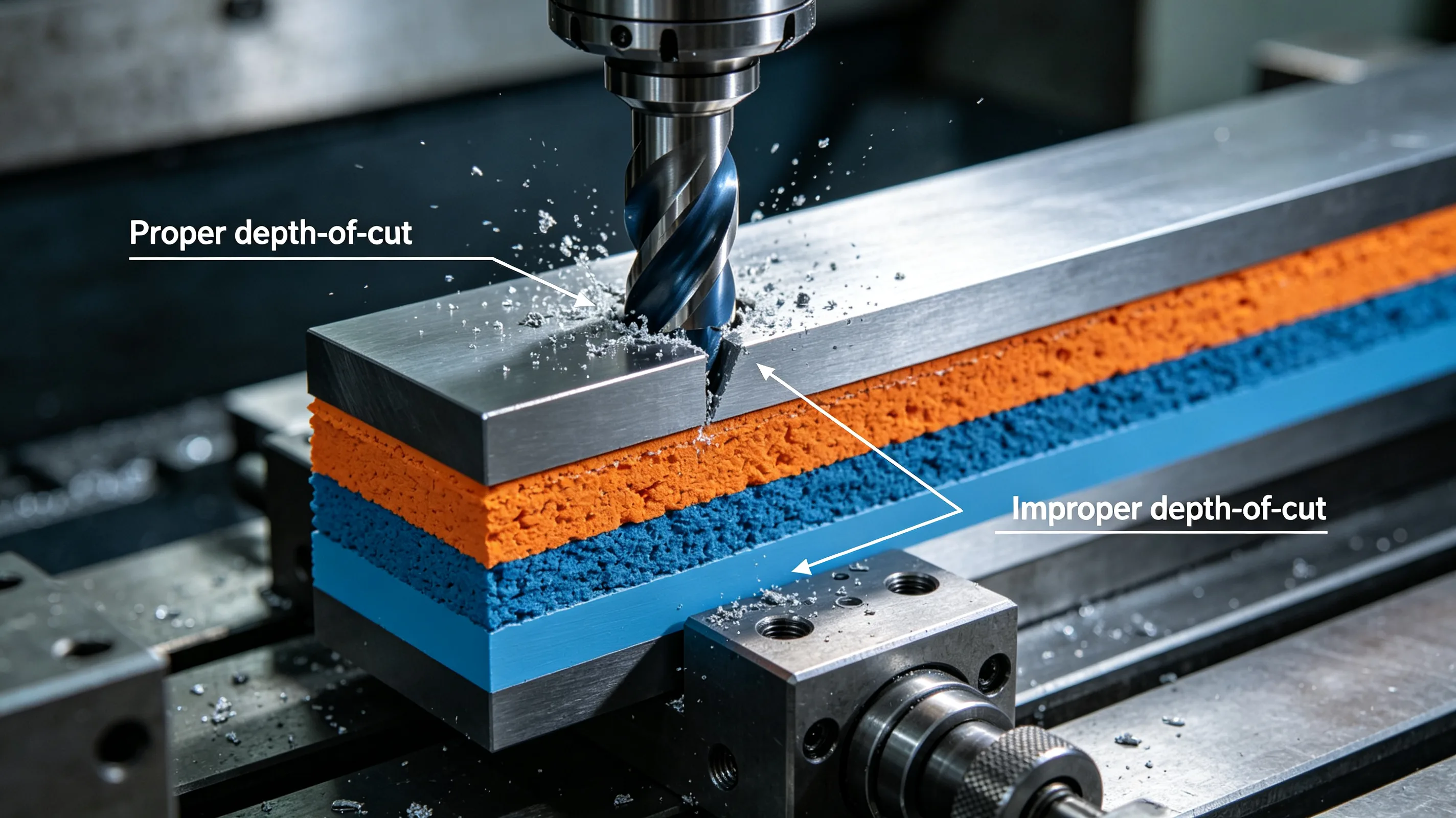
The work-hardened surface layer directly affects tool wear in subsequent passes. When a tool enters a cut, the first material it encounters is not the bulk titanium but a surface that can be 20 to 40 percent harder. The tool must cut through this hardened case before reaching the softer bulk material, creating a sudden increase in cutting force at the point of entry. This force spike is particularly damaging to the tool edge at the depth-of-cut line, where localized notching wear develops.
The wear pattern that results — a groove at the depth-of-cut mark — is characteristic of titanium machining and is one of the most common reasons for premature tool rejection. Once the notching reaches a critical depth, it acts as a stress concentration point, and the tool edge can fracture catastrophically. This is why in thin-wall titanium components where multiple passes are required, the first finishing pass often shows the most rapid tool wear, even though the material removal rate is lower than in roughing.
Surface integrity is affected in ways that go beyond hardness. The deformed subsurface layer contains residual stresses that can be either compressive or tensile depending on cutting conditions. Compressive residual stresses are generally beneficial for fatigue life, which is why some aerospace specifications require compressive stress at the surface. But the strain-hardened layer also contains microstructural damage — deformed grain boundaries, dislocation tangles, and in some cases, microcracks — that can act as fatigue initiation sites if not removed by subsequent processing.
For components that will undergo post-machining operations such as welding or heat treatment, the work-hardened layer can produce unexpected results. The hardened surface may not respond to heat treatment in the same way as the bulk material, leading to inconsistent mechanical properties across the part cross-section. Some aerospace process specifications therefore include a chemical milling or light etching step after roughing to remove the strain-affected layer before final heat treatment. Quality systems used in aerospace titanium manufacturing typically document these post-roughing processing steps as part of the controlled process specification.
Process parameters that control work hardening depth
Feed rate is the most direct control parameter for work hardening depth. Higher feed rates increase the chip load and the depth of deformation below the surface. In roughing operations where material removal is the primary objective, some work hardening is inevitable, and the goal is to keep the hardened layer depth consistent rather than to eliminate it entirely. In finishing operations, lower feed rates reduce the deformation depth, but the tool is cutting through the hardened layer left by roughing, so the benefits are partly offset.
Cutting speed has a more complex relationship with work hardening than with tool wear. Higher cutting speeds increase the temperature at the shear zone, and the higher temperature can thermally soften the subsurface layer, reducing the net hardening effect. But higher speeds also increase tool wear, and the worn tool generates higher cutting forces that increase subsurface deformation. The net effect depends on which factor dominates, and this varies with the specific tool grade, coating, and coolant effectiveness.
Tool edge preparation matters more for work hardening than for most other machining outcomes. A sharp cutting edge produces a clean shear zone with minimal subsurface deformation. A worn or honed edge increases the deformation zone below the surface because the material is pushed rather than sheared. The difference in work hardening depth between a sharp and a slightly worn tool can be a factor of two to three, which is why tool change discipline is important for maintaining consistent surface integrity across a production run.
Coolant delivery affects work hardening primarily through temperature control. When coolant flow is insufficient, the temperature at the shear zone rises, and the surface layer can experience both thermal softening and strain hardening simultaneously. The competing effects can produce an unstable surface condition where hardness varies unpredictably across the part. Consistent high-pressure coolant delivery, maintained above 50 bar at the tool interface, helps stabilize the thermal conditions and produces a more uniform subsurface condition.
Work hardening in thin-wall and complex geometries
Thin-wall titanium components present a particular challenge for work hardening control because the wall stiffness is low enough that the wall deflects under cutting forces. When a thin wall deflects during a cut, the tool engagement changes in an uncontrolled way — the effective depth of cut varies along the wall height, and the cutting force distribution shifts. The result is a work-hardened layer of varying depth across the wall surface, which makes subsequent finishing passes unpredictable.
In deep pockets and cavities, work hardening accumulates at the bottom corners where tool access is restricted and coolant delivery is least effective. The corner radius of the tool creates a zone where the cutting speed approaches zero at the center of the radius, and the material is pushed rather than sheared. This burnishing action generates a localized hardened zone that can be two to three times harder than the adjacent surfaces. In aerospace components where fatigue performance depends on uniform surface condition, these corner zones are often the location of early crack initiation in service.
For complex geometries with multiple features requiring different tool orientations, the work hardening pattern becomes a superposition of effects from each toolpath. A surface that has been machined by a face mill, then a ball end mill, then a finishing pass with a different tool will have a layered work hardening structure that is difficult to predict from any single operation in isolation. Production planning for such components should include a consistent roughing and finishing strategy that minimizes the number of tool changes on critical surfaces.
Table 1: Work hardening depth by cutting condition (Ti-6Al-4V, typical ranges)
| Condition | Affected layer depth | Hardness increase | Primary mechanism |
|---|---|---|---|
| Sharp tool, light finish cut | 50–00 μm | 10–0 HV | Strain from shear |
| Worn tool, finishing | 150–50 μm | 20–0 HV | Strain + friction |
| Heavy roughing, fresh tool | 200–00 μm | 30–0 HV | High strain rate |
| Heavy roughing, worn tool | 300–00 μm | 40–0 HV | Strain + thermal + friction |
| Burnishing (corner radius) | 100–00 μm | 50–0 HV | Compressive deformation |
Table 2: Parameter adjustments to reduce work hardening
| Parameter | Adjustment | Effect on hardening | Trade-off |
|---|---|---|---|
| Feed rate | Reduce 20–0% | Reduces depth 30–0% | Longer cycle time |
| Tool sharpness | Replace at 0.15 mm flank wear | Reduces depth 40–0% | More tool changes |
| Coolant pressure | Increase above 50 bar | Stabilizes hardness variation | Higher pump capacity |
| Radial engagement | Reduce 30% | More uniform depth | More passes required |
| Climb vs conventional | Use climb milling | Reduces exit-zone hardening | Requires rigid setup |
For work-hardening-sensitive components, request a process review and our engineers will define the roughing and finishing strategy for your geometry.