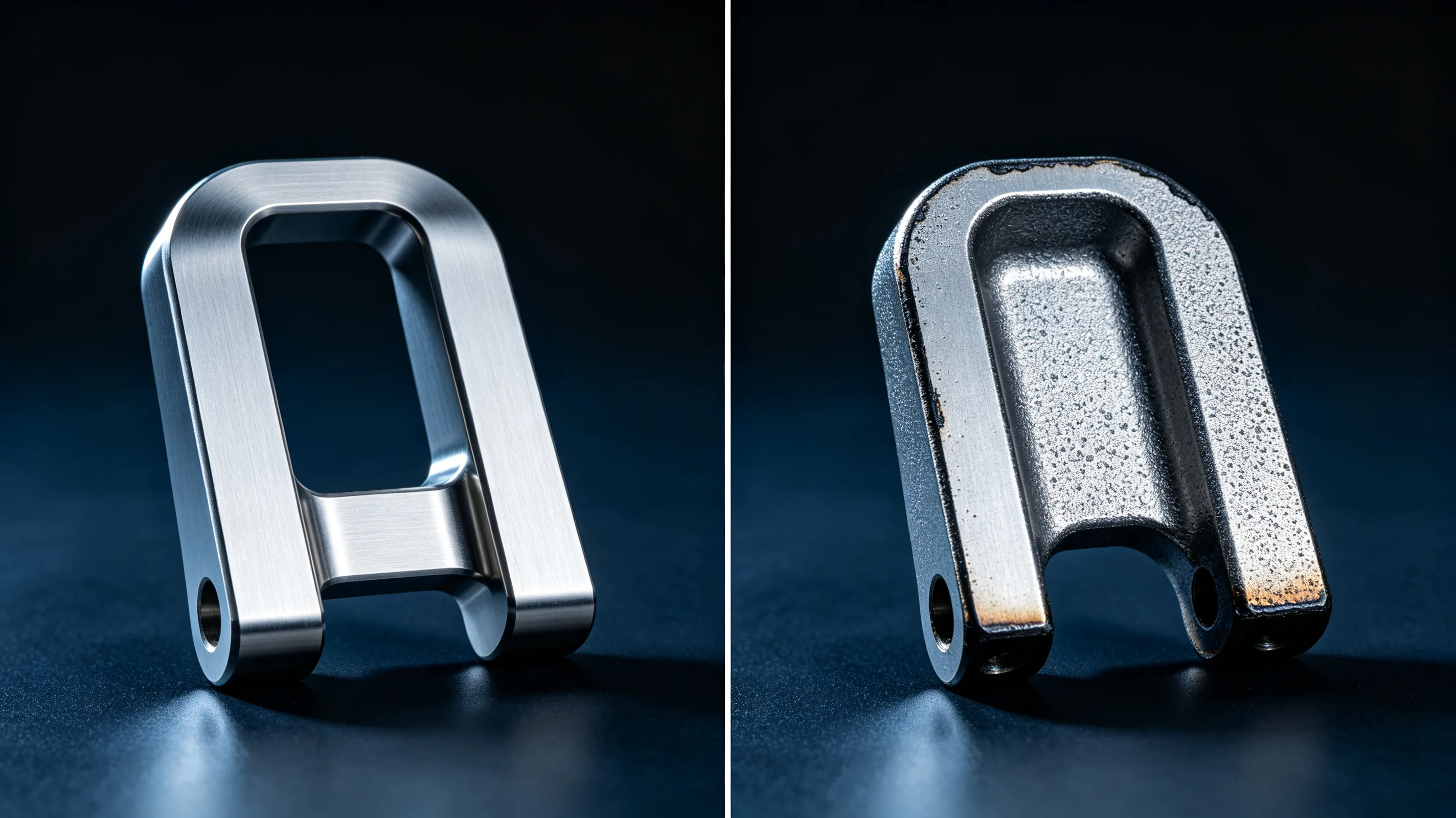
How to Machine Thin-Wall Titanium Parts Without Distortion
Executive summary: Thin-wall titanium parts distort during machining because the material has a low elastic modulus and high cutting forces relative to wall stiffness. The distortion is elastic deflection under load, not permanent plastic deformation, which means it returns when the tool moves away. The challenge is that this springback makes the final dimensions unpredictable unless the process compensates for it. Controlling distortion requires a sequence of roughing, stress-relief, semi-finishing, and finishing passes; low-radial-engagement toolpaths; conformal or potting fixtures; and in-process measurement with toolpath compensation. The goal is not to eliminate deflection but to manage it so the part is within tolerance after the tool leaves the surface.
Why thin titanium walls distort so easily
Titanium has an elastic modulus of approximately 110 GPa. Steel is around 200 GPa and aluminum is 70 GPa. At first glance titanium seems stiffer than aluminum, but its density is also higher. On a stiffness-per-weight basis, titanium is competitive, but in absolute terms a thin titanium wall deflects more than an equivalent steel wall and similarly to an aluminum wall of the same geometry.
The more important factor is the cutting force. Titanium requires higher cutting forces than aluminum because of its strength, and those forces act on a wall that has little stiffness. A thin titanium wall can deflect 0.05 to 0.20 mm under normal finishing forces. After the tool passes, the wall springs back, leaving material where the tool appeared to have cut to depth. The result is walls that are thicker than programmed and pockets that are undersized.
Residual stress adds another complication. The machining process redistributes stress in the workpiece. As material is removed from one side, the remaining wall may curl or twist slightly as it reaches equilibrium. This distortion can appear hours after machining if the part is not stress-relieved between operations.
The role of wall aspect ratio
The governing geometric parameter is aspect ratio: wall height divided by wall thickness. Stiffness decreases with the cube of thickness reduction, so small thickness changes produce large deflection changes. Walls with aspect ratios below 8:1 can usually be machined with conventional strategies. Walls between 8:1 and 12:1 require reduced radial engagement and fixture support. Walls above 12:1 typically need specialized fixturing, multiple finish passes, and process compensation. Walls above 15:1 should be redesigned if possible.
Table 1: Thin-wall machining strategy by aspect ratio for Ti-6Al-4V
| Aspect ratio | Process regime | Typical deflection | Required strategy |
|---|---|---|---|
| Below 8:1 | Stable | < 0.02 mm | Standard toolpaths and fixturing |
| 8:1 to 12:1 | Transitional | 0.02–0.05 mm | Low radial engagement, fresh tools |
| 12:1 to 15:1 | Deflection-dominated | 0.05–0.12 mm | Conformal fixtures, adaptive toolpaths |
| Above 15:1 | Redesign recommended | > 0.12 mm | Add ribs, increase thickness, or use alternative process |
Toolpath strategies that minimize distortion
The toolpath controls how force is applied to the wall. Conventional contour-parallel paths produce variable engagement at corners and internal features, creating force spikes. Adaptive or trochoidal toolpaths maintain constant radial engagement, which keeps cutting force steady. Steady force is easier to compensate than varying force.
For thin walls, radial engagement should be limited to 5 to 15 percent of the tool diameter during finishing. This reduces the maximum cutting force while still maintaining chip formation. Axial depth can be full slot depth in many cases because the tool is stiffer axially than radially. The combination of low radial engagement and full axial depth is a standard strategy for thin-wall titanium finishing.
Roughing should leave consistent stock on all walls. Uneven stock causes uneven semi-finishing forces, which create uneven springback. A common target is 1.0 to 1.5 mm of stock after roughing, removed in two or three semi-finish passes before the final finish pass. Each pass should use a sharp tool and a toolpath direction that avoids pushing the wall in the same direction repeatedly.
Fixturing that supports the wall
Fixture design is often the deciding factor in thin-wall titanium machining. Standard clamps and vises support the bulk of the part but leave thin walls unsupported. The unsupported wall deflects away from the tool during cutting and vibrates at high frequency, producing poor surface finish and dimensional error.
Conformal fixtures match the geometry of the part and support thin walls along their full height. They are machined from aluminum or urethane and designed to be slightly smaller than the part so the walls are held firmly without being crushed. For very thin or complex walls, potting the part in a low-melt alloy or polymer provides uniform support from all sides. The potting material is removed after machining by melting or dissolving.
Strategic support ribs are another option. If the design allows, leaving temporary ribs that connect thin walls during machining adds stiffness. The ribs are machined away in the final operation. This approach requires design agreement because the ribs may leave small witness marks or require cleanup.
Compensating for springback
Even with perfect toolpaths and fixtures, some springback remains. The practical solution is to measure the springback and compensate the toolpath. A common workflow is to run a first-article finish pass, measure the wall thickness or pocket size, calculate the deviation, and offset the toolpath by that amount for the remaining parts.
For production quantities, in-process probing can automate this adjustment. The machine measures a reference feature after semi-finishing, calculates the actual deflection, and updates the finish pass coordinates. This closed-loop approach is especially valuable when material properties vary between heats or when thermal expansion affects the part during machining.
Table 2: Distortion control methods and when to use them
| Method | Best for | Limitation |
|---|---|---|
| Low radial engagement | All thin-wall finishing | Longer cycle time |
| Conformal fixture | Walls with predictable geometry | Longer setup and fixture cost |
| Potting in low-melt alloy | Very thin or complex walls | Added process step and cleanup |
| Temporary support ribs | Walls connected by design | Requires design approval |
| Toolpath compensation | Repeatable production | Requires first-article measurement |
| Stress relief between operations | Parts with high residual stress | Added lead time and cost |
Process sequence for thin-wall titanium
A robust process sequence begins with stress-relief of the raw material if it has been heavily cold-worked or forged. Roughing removes the bulk of material while leaving generous stock on thin walls. A stress-relief cycle between roughing and semi-finishing stabilizes the part and prevents delayed distortion. Semi-finishing brings thin walls close to final dimension in several light passes. Finishing removes the last 0.1 to 0.2 mm with sharp tools and low engagement.
Thermal management is part of the sequence. Titanium parts heat up during machining, and the thermal expansion changes dimensions. Allowing the part to cool to a consistent temperature before finishing improves repeatability. For tight tolerances, some shops machine finishing passes in a temperature-controlled environment or use coolant temperature control.
For general thin-wall guidelines and wall thickness rules, see the thin wall titanium machining guidelines. For broader titanium DFM rules, see the titanium CNC design guide.
Practical rules for distortion-free thin-wall parts
Rule 1 — Do not design thin walls thinner than the process can hold. A wall that is too thin cannot be saved by clever machining. If the aspect ratio exceeds 15:1, redesign before releasing to manufacturing.
Rule 2 — Sequence operations to release stress gradually. Remove material symmetrically, leave equal stock on opposite walls, and add a stress-relief cycle when roughing removes significant material.
Rule 3 — Validate with first-article measurement and compensate. Assume springback will occur. Measure the first part, calculate the deviation, and update the program before running production.
To discuss thin-wall titanium machining for a specific component, request a manufacturing review.