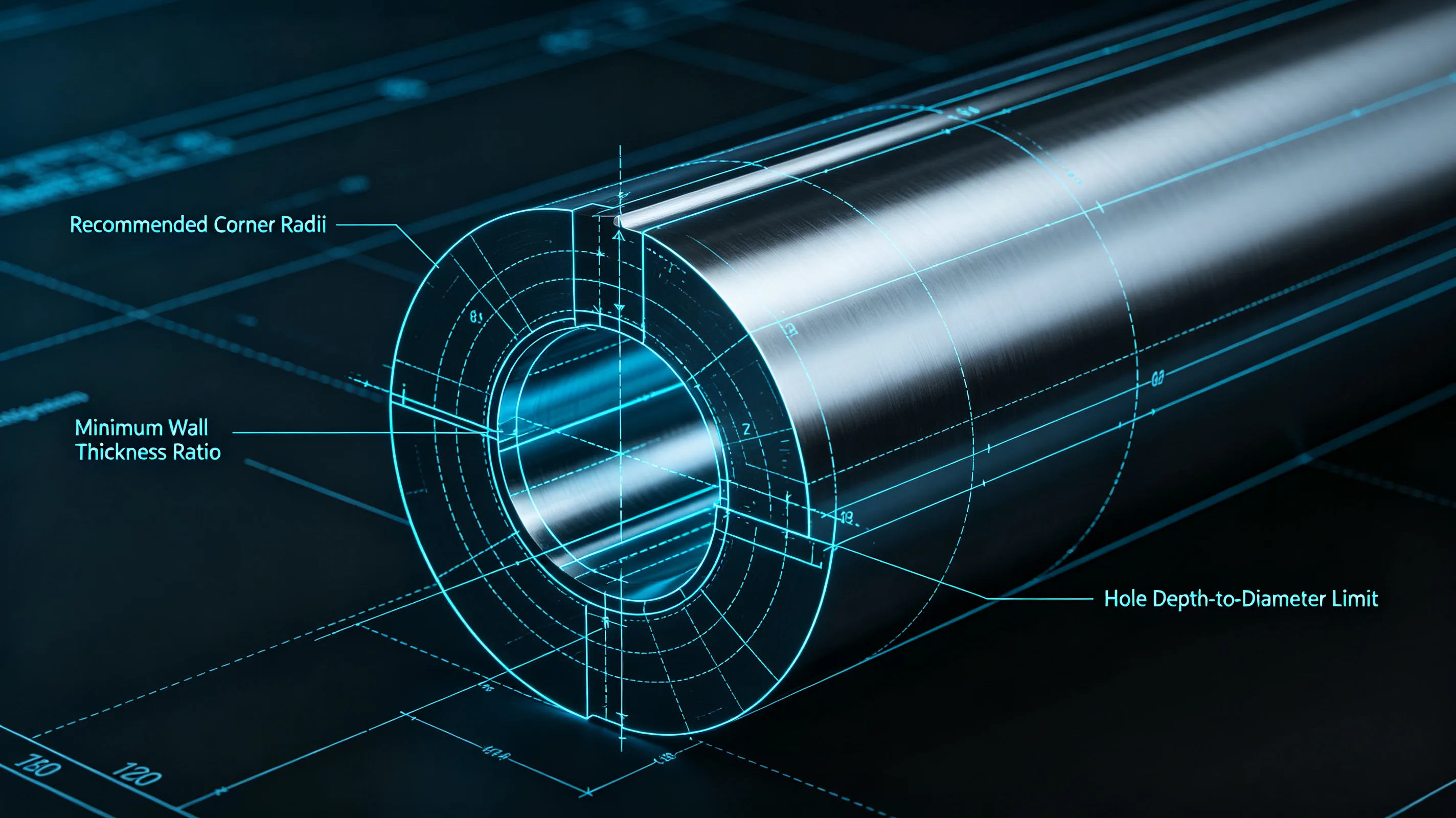
Designing components for titanium CNC machining requires rules that differ from design guidelines for steel, aluminum, or even stainless steel. The material’s low thermal conductivity, high cutting forces, elastic springback, and work hardening behavior create constraints on geometry that are not present in more machinable materials. Applying design rules developed for other metals to titanium components leads to parts that are difficult to machine, expensive to produce, or impossible to hold to tolerance. This guide provides geometry-specific design rules for titanium CNC machining, organized by feature type. The machining challenges that create these design constraints are analyzed in detail in the article on why titanium is difficult to machine, and our titanium CNC machining services page describes how these design rules are applied in production.
- Wall thickness guidelines for titanium
- Minimum internal and external radii
- Pocket depth limits and aspect ratios
- Tool accessibility and feature spacing
- Tolerance capability by feature type
- Design-for-manufacturability rules specific to titanium
Wall thickness guidelines for titanium
Wall thickness in titanium components directly determines the machining strategy required and the achievable dimensional accuracy. Thin walls deflect under cutting forces, and the deflection increases with the cube of the wall height-to-thickness ratio.
For walls with an aspect ratio — height divided by thickness — below 8 to 1, conventional machining with standard fixturing is typically adequate. Walls in this range have sufficient stiffness to resist cutting forces without significant deflection, and the springback after machining is predictable and manageable.
For aspect ratios between 8 to 1 and 12 to 1, the wall will deflect noticeably during cutting. Machining these walls requires reduced radial engagement, multiple semi-finishing passes, and fixturing that supports the wall as close to the cut zone as possible. The dimensional tolerance that can be maintained on walls in this range is approximately 0.05 to 0.10 mm.
For aspect ratios between 12 to 1 and 15 to 1, the wall deflection becomes the primary process control challenge. Successful machining requires trochoidal or adaptive toolpaths, hydraulic or conformal fixturing, and in-process measurement with toolpath compensation. Tolerances below 0.10 mm are difficult to maintain consistently.
For aspect ratios above 15 to 1, the wall is too flexible for conventional machining approaches. These features should be redesigned if possible — adding intermediate support ribs, increasing the wall thickness, or changing the material to one with a higher elastic modulus. If the geometry cannot be changed, specialized approaches such as robotic part manipulation, low-melt alloy potting, or Electrical Discharge Machining should be evaluated.
The minimum practical wall thickness for titanium CNC machining depends on the wall height. For walls 10 mm high, a minimum thickness of 0.5 mm is achievable with careful process control. For walls 25 mm high, the minimum increases to approximately 1.0 mm. For walls 50 mm high, the minimum is approximately 2.0 mm. These values assume the wall is part of a rigid overall structure — isolated thin webs require greater thickness.
Minimum internal and external radii
Internal corner radii in titanium components should be designed to match available tool diameters. A sharp internal corner — one that requires a smaller radius than the tool can produce — forces the use of a smaller tool, which has less rigidity and is more prone to deflection and chatter.
The general rule for titanium is that the internal corner radius should be at least 1.5 times the tool diameter. For example, a 6 mm internal radius allows the use of a 10 mm diameter tool (radius = 5 mm) with some margin. This ratio ensures that the tool engages the corner at a manageable angle and that the cutting forces remain stable.
For deep pockets where tool length-to-diameter ratios exceed 4 to 1, the internal radius should be increased to 2 times the tool diameter to compensate for the reduced tool stiffness at longer extensions. A 6 mm internal radius that is adequate at a 3 to 1 tool extension may produce chatter at a 5 to 1 extension.
External radii are less constrained than internal radii because the tool can approach from outside the material boundary. The minimum external radius is limited primarily by the tool diameter and the need to maintain smooth tool motion through the corner. An external radius of 1 to 2 mm is generally achievable with standard tooling.
The transition between surfaces — where a horizontal floor meets a vertical wall — should include a radius or chamfer to eliminate the sharp corner. Sharp internal corners at floor-wall transitions create stress concentrations in the toolpath where the tool engagement increases suddenly, and in the finished part they are potential fatigue initiation sites. A 0.5 to 1.0 mm radius at floor-wall transitions is standard practice.
Pocket depth limits and aspect ratios
Pocket depth in titanium is limited by tool stiffness, chip evacuation, and coolant delivery. As the pocket depth increases, the tool must extend further from the holder, reducing its rigidity and increasing deflection. The chip evacuation path becomes longer, and the coolant must travel further to reach the cutting edge.
For general-purpose pocket machining in titanium, a pocket depth of 2 to 3 times the tool diameter is practical with standard tooling. A 12 mm diameter end mill can reasonably machine pockets 24 to 36 mm deep. Beyond this depth, specialized approaches are required.
For pocket depths of 3 to 5 times the tool diameter, the tool should be designed with a reduced neck diameter to provide clearance for chip evacuation. The reduced neck allows chips to flow past the tool more freely and reduces the risk of chip packing. Coolant delivery should be through the spindle to ensure that the cutting edge is adequately lubricated at depth.
For pocket depths exceeding 5 times the tool diameter, the machining strategy shifts from end milling to techniques that minimize tool overhang. This may involve machining from both sides of the component, using extended-reach toolholders with vibration damping, or employing EDM for the deepest features.
Pocket floor flatness is affected by tool deflection and thermal expansion. For pockets with tight floor flatness requirements, the finishing pass should be taken with a new or freshly indexed tool, and the floor should be machined in a single continuous pass to avoid witness marks at toolpath transitions.
Tool accessibility and feature spacing
Tool accessibility determines whether a feature can be machined with a standard tool path or requires specialized tooling or multiple setups. Features that are accessible from a single direction — all features on the same side of the component — can typically be machined in one setup. Features on opposite sides require either a second setup or a 5-axis machine with the ability to reach around the component.
For components machined on 3-axis machines, the tool access direction is vertical, and features on the top surface are accessible while features on the side or bottom are not. Undercuts — features where the tool must reach under an overhanging surface — cannot be machined with standard 3-axis approaches and require either 5-axis machining, EDM, or a design change.
The spacing between adjacent features affects the toolpath and the tool diameter that can be used. The minimum distance between two pocket walls should be at least the diameter of the largest tool that can reasonably machine both features. If the spacing is less than the tool diameter, one wall may be machined with the side of the tool while the other is machined with the bottom, creating different surface conditions on the two walls.
Deep narrow slots in titanium should be designed with a width-to-depth ratio that allows the slot to be machined with a tool that has adequate rigidity. For slots narrower than 6 mm, the depth should be limited to approximately 3 times the slot width. For wider slots, the depth limit increases proportionally.
Tolerance capability by feature type
The tolerances that can be held in titanium machining depend on the feature type, the material condition, and the machining strategy. General tolerance capabilities for titanium components are approximately one-half to one ISO grade coarser than for equivalent features in aluminum or steel.
For linear dimensions between machined surfaces, standard commercial tolerances of ±0.10 mm are readily achievable. Precision tolerances of ±0.05 mm are achievable with careful process control, and high-precision tolerances of ±0.025 mm are possible for specific features with dedicated tooling and in-process measurement.
For hole positions, the achievable tolerance depends on the hole depth and diameter. Shallow holes — depth less than 3 times the diameter — can be held to ±0.05 mm position tolerance. Deep holes require progressively looser tolerances as the depth increases.
For surface flatness, a general rule is that flatness of 0.05 mm per 100 mm of surface length is achievable for most titanium components. Tighter flatness requirements are possible with stress-relieved material and controlled machining sequences that manage residual stress redistribution.
For concentricity and coaxial features, the achievable tolerance depends on whether the features can be machined in a single setup. Features machined in one setup can typically hold 0.025 to 0.05 mm concentricity. Features requiring multiple setups are limited by the setup repeatability and typically achieve 0.05 to 0.10 mm.
Surface finish in titanium is typically specified as Ra 0.8 to 1.6 μm for standard machined surfaces, Ra 0.4 to 0.8 μm for precision surfaces, and Ra 0.2 to 0.4 μm for high-precision surfaces that may require post-machining processing. The article on achieving Ra 0.4μm provides the parameter selection details for meeting specific finish requirements, and the tolerance guide covers dimensional tolerance selection for titanium components in more detail.
Design-for-manufacturability rules specific to titanium
Several design practices that are acceptable for steel or aluminum components should be avoided in titanium designs.
Uniform wall thickness should be maintained wherever possible. Transitions between thick and thin sections create thermal gradients during machining that lead to differential expansion and distortion. If a thickness change is unavoidable, the transition should be gradual — a taper of 1 to 3 degrees rather than a step change.
Deep holes should be specified as through-holes rather than blind holes when the design allows. Through-holes provide an exit path for coolant and chips, improving tool life and reducing the risk of chip packing and tool failure. Blind holes deeper than 3 times the diameter should include a flat bottom or a standard drill point angle to allow the tool to cut to depth without side loading.
Threaded holes in titanium should be designed with sufficient thread length to distribute the load over multiple threads. The minimum thread engagement for titanium is typically 1.5 to 2 times the bolt diameter, compared to 1.0 to 1.5 times for steel. Thread rolling rather than thread cutting is preferred for titanium threads because the cold working process produces a stronger thread form with better fatigue resistance.
Sharp internal corners should be avoided at all locations where the component will experience cyclic loading. The combination of the stress concentration from the sharp corner and the notch sensitivity of titanium can reduce fatigue life significantly. A minimum fillet radius of 0.5 mm is standard, with larger radii preferred for highly loaded features.
The datum structure for titanium components should be designed to allow all critical features to be machined in a single setup wherever possible. Multiple setups introduce setup error that compounds the inherent variability of titanium machining. Datums should be located on surfaces that are accessible from the primary machining direction and that remain stable throughout the machining process.
Component design should allow for roughing and finishing passes with a minimum of 0.3 to 0.5 mm of stock remaining for finishing. This allowance provides sufficient material for the finishing tool to cut cleanly through the work-hardened surface layer left by roughing. Designs that leave minimal finishing stock increase the risk of the finishing tool encountering hardened surface material and wearing prematurely.
To have your design reviewed for machinability before quoting, contact our engineering support team, and validate the tolerances in your drawing with the CNC tolerance checker.
Table 1: Wall thickness guidelines by aspect ratio
| Aspect ratio (height/thickness) | Machining approach | Achievable tolerance | Fixturing requirement |
|---|---|---|---|
| Below 8:1 | Standard approach | ±0.05 mm | Standard vise or clamp |
| 8:1 to 12:1 | Reduced engagement, multiple passes | ±0.05–0.10 mm | Conformal or hydraulic |
| 12:1 to 15:1 | Trochoidal toolpaths, in-process measurement | ±0.10–0.15 mm | Potting or custom fixture |
| Above 15:1 | Redesign required or specialized process | Not reliably achievable | Specialist process design |
Table 2: Tolerance capability by feature type in titanium
| Feature type | Standard tolerance | Precision tolerance | Limiting factor |
|---|---|---|---|
| Linear dimensions | ±0.10 mm | ±0.05 mm | Machine accuracy, thermal stability |
| Hole position | ±0.10 mm | ±0.05 mm | Tool deflection |
| Hole diameter | H7–H8 | H6–H7 | Tool wear, thermal expansion |
| Surface flatness | 0.05 mm/100mm | 0.02 mm/100mm | Residual stress, fixturing |
| Concentricity (single setup) | 0.05 mm | 0.025 mm | Machine spindle accuracy |
| Wall thickness | ±0.05 mm | ±0.025 mm | Springback, tool deflection |