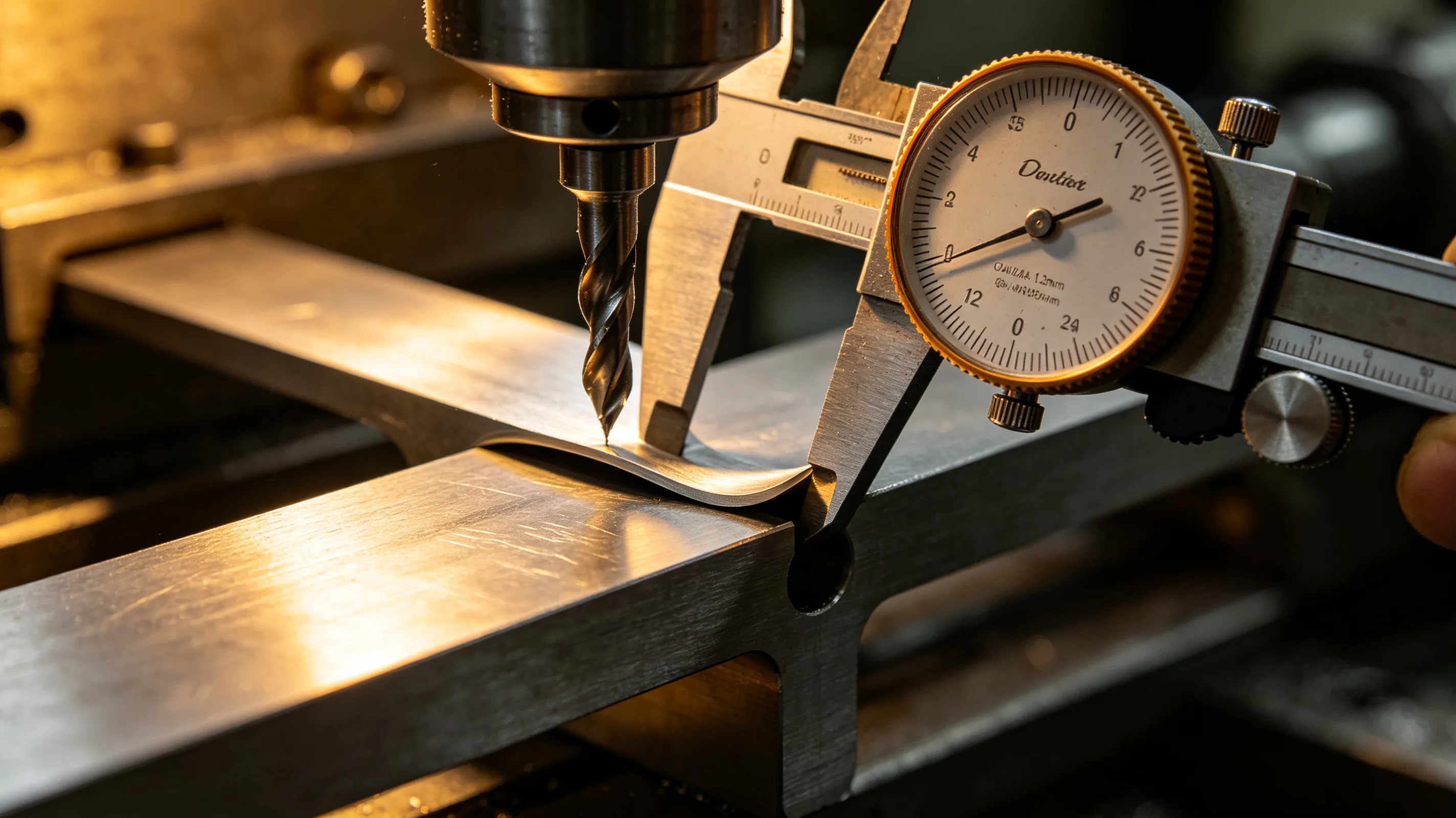
Thin-wall titanium components present the most demanding combination of design and manufacturing challenges. The low elastic modulus of titanium means that thin walls deflect more under cutting forces than equivalent steel features, and the material’s work hardening behavior means that each pass changes the surface condition for the next pass. Successful thin-wall machining requires a process strategy that accounts for these factors from the first roughing pass through the final finishing cut. For the overall design rules that apply to all titanium features, see the titanium CNC design guide, and our 5-axis CNC machining services apply these strategies on production thin-wall components.
How wall geometry determines process limits
The governing parameter for thin-wall machining is the aspect ratio — the wall height divided by the wall thickness. This ratio determines the wall stiffness, which decreases with the cube of the thickness reduction. A wall that is 20 mm high and 2.0 mm thick has an aspect ratio of 10 to 1. Reducing the thickness to 1.0 mm increases the aspect ratio to 20 to 1 and reduces the stiffness by a factor of eight.
The stiffness reduction is not linear, which creates a process control challenge. The first roughing passes on a thick wall produce minimal deflection, and the part behaves predictably. As the wall approaches its final thickness, each successive pass removes less material but produces more deflection. The process transitions from a stiffness-dominated regime to a deflection-dominated regime at approximately 10 to 1 aspect ratio for titanium.
The cutting force generated during a finishing pass on a thin titanium wall is typically 100 to 300 N, depending on the tool diameter, depth of cut, and feed rate. A wall with a 10 to 1 aspect ratio deflects 0.02 to 0.05 mm under this force. A wall with a 15 to 1 aspect ratio deflects 0.08 to 0.15 mm. The deflected wall returns to near its original position after the tool passes, but the springback leaves a dimensional error that must be accounted for in the CAM program.
Toolpath strategies for thin-wall deflection control
The toolpath strategy for thin-wall titanium should minimize the radial cutting force and distribute it evenly along the wall. Trochoidal toolpaths that maintain constant radial engagement are the standard approach. The radial engagement should be set at 5 to 15 percent of the tool diameter for finishing passes on thin walls, compared to 20 to 30 percent for standard wall sections.
Conventional contour-parallel toolpaths, where the tool follows the wall contour with a constant offset, produce varying engagement at corners and transitions. The engagement spike at an internal corner can double or triple the cutting force momentarily, and on a thin wall this force spike produces a corresponding deflection spike that leaves a visible mark on the finished surface.
Adaptive toolpaths that adjust the feed rate based on the instantaneous engagement angle provide more consistent deflection control. The feed rate is reduced in high-engagement zones to maintain constant cutting force, and increased in low-engagement zones to maintain productivity. The result is a more uniform deflection pattern that can be compensated more accurately in the CAM program.
Climb milling is preferred for thin-wall titanium finishing because it directs the cutting forces into the wall support structure rather than pulling the wall away from it. In climb milling, the chip thickness is maximum at the point of entry and decreases toward exit, so the cutting force is highest when the wall is most rigidly supported and decreases as the tool moves toward the unsupported edge.
Fixturing approaches for thin-wall support
The fixturing approach has a larger effect on thin-wall machining success than any other process parameter. A wall that is not adequately supported will deflect under cutting forces regardless of the toolpath strategy.
Vacuum fixturing is effective for thin-wall components with large flat surfaces. The vacuum holds the component uniformly across its surface, distributing the clamping force and eliminating the localized deformation from point clamps. Vacuum pressure of 60 to 80 kPa is typical, providing 6 to 8 tonnes per square meter of holding force.
Low-melt-temperature alloy or polymer potting provides the most uniform support for complex thin-wall geometries. The component is placed in a fixture frame, and the molten potting material is poured around it. After solidification, the potting material supports the thin walls uniformly from all sides. The potting material is removed after machining by melting or chemical dissolution.
For production runs, custom fixture plates with conformal pockets that match the component geometry provide the best combination of support and accessibility. The pocket is machined to a depth just below the wall height, and the component is clamped into the pocket with the thin walls supported along their entire height.
Pass sequence for thin-wall stability
The pass sequence for thin-wall titanium should follow a progressive reduction strategy. The roughing passes remove the bulk of the material with deep cuts and high material removal rates, leaving 1.0 to 1.5 mm of stock on the thin walls. The semi-finishing passes remove stock in 0.3 to 0.5 mm increments, progressively reducing the cutting forces as the wall becomes thinner.
The finishing pass should remove 0.1 to 0.2 mm of stock with a sharp tool at low radial engagement. The tool should be new or freshly indexed to ensure that the cutting edge is sharp and that the cutting forces are as low as possible. A worn tool that is acceptable for standard tolerance work will produce excessive deflection on thin-wall features.
Between the semi-finishing and finishing passes, allowing the part to return to thermal equilibrium improves dimensional stability. The heat generated during semi-finishing causes local thermal expansion that masks the true deflection. Allowing the part to cool before the finishing pass reveals the actual deflection pattern and allows the CAM compensation to be more accurate.
For extremely thin walls — aspect ratios above 12 to 1 — multiple finish passes with progressively lighter cuts are more effective than a single finish pass. The first finish pass at 0.15 mm removes the work-hardened surface layer from semi-finishing. The second at 0.10 mm removes the deflection error from the first pass. The third at 0.05 mm produces the final surface with minimal cutting force.
Table 1: Thin-wall machining parameters by aspect ratio (Ti-6Al-4V)
| Aspect ratio | Radial engagement | Finishing stock | Tool condition | Expected deflection |
|---|---|---|---|---|
| Below 8:1 | 15–0% | 0.3–0.5 mm | Standard sharp | <0.02 mm |
| 8:1 to 12:1 | 10–5% | 0.2–0.3 mm | Fresh tool | 0.02–0.05 mm |
| 12:1 to 15:1 | 5–0% | 0.15–0.2 mm | New tool | 0.05–0.10 mm |
| Above 15:1 | 3— % | 0.1–0.15 mm | New tool, multiple passes | 0.10–0.20 mm |
For thin-wall components where deflection control is critical, request a process study and our engineers will define the toolpath and fixturing strategy for your geometry.