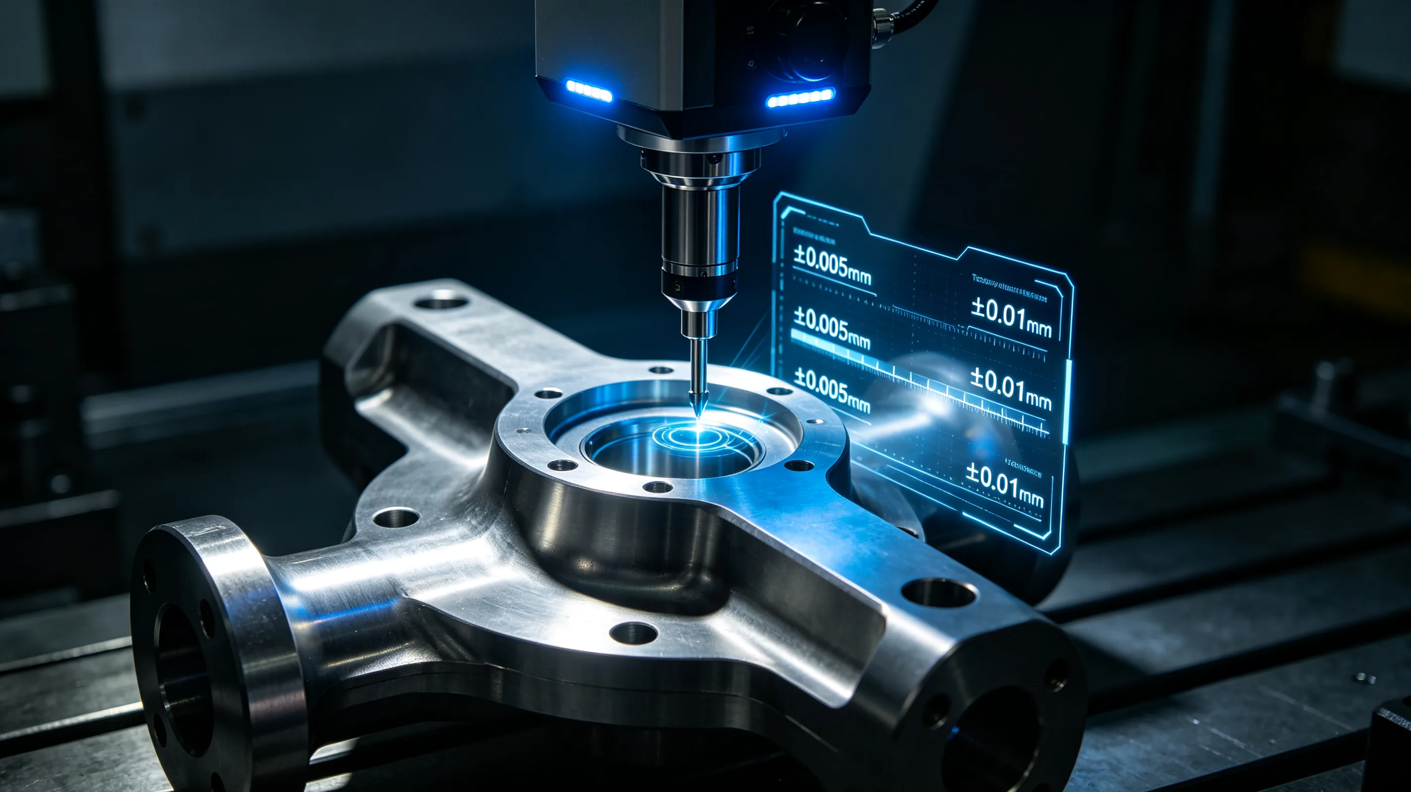
Specifying tolerances on titanium components requires an understanding of how the material’s physical properties affect machining accuracy. Titanium’s low thermal conductivity, elastic springback, and residual stress behavior all influence the achievable dimensional precision in ways that differ from steel or aluminum. Applying standard tolerance guidelines developed for other materials to titanium components leads to either unachievable specifications or unnecessarily conservative designs. For the broader design context, see the titanium CNC design guide.
General tolerance capability for titanium
The base tolerance capability for titanium CNC machining on standard 3-axis and 5-axis machine tools is approximately ±0.05 mm for linear dimensions under 100 mm. This assumes the component is machined from stress-relieved material on a machine tool in good condition with appropriate tooling and coolant systems.
For dimensions over 100 mm, the achievable tolerance relaxes by approximately 0.01 mm per 50 mm of additional length. A 200 mm dimension can typically be held to ±0.07 mm, while a 400 mm dimension requires approximately ±0.10 mm. The relaxation is driven by thermal expansion of the workpiece and the machine tool structure over the longer machining cycle required for larger components.
Tighter tolerances of ±0.025 mm are achievable for specific features with dedicated process control — in-process probing, temperature-controlled coolant, and multiple finishing passes. However, applying tight tolerances to every feature on a component increases machining time and cost disproportionately. A component with a single tight-tolerance feature and otherwise standard tolerances is less expensive to produce than one where all features are specified at the tightest achievable limit.
Tolerances tighter than ±0.025 mm require specialized approaches. Jig grinding, hard turning, or post-machining processes such as abrasive flow machining may be needed. These processes add significant cost and should be specified only when the functional requirement genuinely demands sub-0.025 mm precision.
Tolerance by feature type
Machined surfaces and milled features — flats, steps, pockets, and contours — can typically be held to ±0.05 mm for general work and ±0.025 mm for precision work. The limiting factor for milled features is usually tool deflection rather than machine accuracy. Features machined with small tools — below 6 mm diameter — require looser tolerances because the tool deflection is proportionally larger.
Turned diameters follow similar limits. External diameters can be held to ±0.025 mm with careful process control. Internal diameters are more challenging because the boring bar deflects under cutting forces, and the achievable tolerance relaxes to ±0.05 mm for depths greater than 3 times the bar diameter.
Hole tolerances depend on the drilling or boring method. Drilled holes in titanium are typically specified at H8 to H9 tolerance. Reamed holes achieve H7. Bored holes with a single-point boring tool achieve H6 to H7. For holes tighter than H6, post-machining processes such as honing or wire EDM are required.
Threaded holes in titanium should be specified with tolerance classes that account for the material’s springback. Internal threads produced by thread milling achieve a class 2B or 3B fit. Threads produced by thread forming — which is preferred for titanium because it cold-works the thread surface and improves fatigue strength — achieve similar tolerance classes but require different tap drill sizes than thread cutting.
Effect of material condition on tolerance capability
The material condition at the time of machining affects the achievable tolerance. Components machined from stress-relieved material hold tighter tolerances than those machined from as-rolled or as-forged material because the residual stress redistribution during material removal is reduced.
For components that will be heat treated after roughing, the roughing operations should be performed with an allowance for dimensional changes during heat treatment. Ti-6Al-4V typically shrinks by 0.05 to 0.10 percent during solution treatment and aging due to the density change from the phase transformation. The rough-machined dimensions should be adjusted to account for this shrinkage so that the final dimensions after heat treatment and finishing are within specification.
The thermal stability of the workpiece during machining affects tolerance consistency over a production run. Components that are roughed and finished in the same setup on a machine without coolant temperature control will experience a gradual drift in dimensions as the machine and workpiece warm up. The first part of a production run may be 0.02 to 0.04 mm different from the last part due to thermal effects alone.
GD&T considerations for titanium
Geometric tolerances in titanium follow the same GD&T standards as other materials, but the achievable values differ. Flatness of 0.05 mm per 100 mm is standard for titanium, with 0.02 mm per 100 mm achievable with stress-relieved material and controlled machining sequences.
Parallelism and perpendicularity are influenced by fixturing stability. Features machined in a single setup can hold 0.025 to 0.05 mm. Features requiring multiple setups are limited by the setup repeatability, typically 0.05 to 0.10 mm.
Concentricity and coaxiality are similarly setup-dependent. Features machined in one setup — such as a bore and an external diameter machined from the same clamping — can hold 0.025 mm. Features that require the part to be repositioned between operations are limited to 0.05 to 0.10 mm.
Profile tolerances for contoured surfaces depend on the surface area and the toolpath strategy. Small contoured surfaces of less than 1000 mm² can hold 0.05 mm profile tolerance. Larger surfaces require 0.10 mm or more, particularly if machined with ball end mills where the cusp height interacts with the tolerance requirement.
Practical tolerance specification guidelines
The most cost-effective approach to tolerance specification for titanium components is to relax tolerances where functional requirements allow and tighten them only where necessary. A typical aerospace titanium component may have 80 percent of its features specified at ±0.10 mm, 15 percent at ±0.05 mm, and 5 percent at ±0.025 mm or tighter. This distribution reflects the reality that most features do not require the tightest achievable tolerance, and specifying all features at the tightest level adds cost without functional benefit.
When specifying tolerances on titanium components, the tolerance should be referenced to a datum structure that can be established in the machining setup. Floating tolerances — where the reference datum is not clearly defined or cannot be accessed in the machining setup — are a common source of inspection disagreements and production delays.
For thin-wall features, the tolerance should account for the expected deflection under cutting forces. Specifying ±0.025 mm on a 15-to-1 aspect ratio wall is unrealistic because the wall deflects more than this under any cutting load. A tolerance of ±0.10 mm is appropriate for such features, with the understanding that tighter tolerances would require a design change or a different manufacturing approach.
Table 1: Achievable tolerances for titanium by feature type
| Feature type | Standard tolerance | Precision tolerance | With post-processing |
|---|---|---|---|
| Milled surface, general | ±0.10 mm | ±0.05 mm | ±0.025 mm |
| Turned diameter, external | ±0.05 mm | ±0.025 mm | ±0.013 mm |
| Turned diameter, internal | ±0.05 mm | ±0.05 mm | ±0.025 mm |
| Drilled hole | H9 | H8 | H7 (reamed) |
| Bored hole | H8 | H7 | H6 |
| Linear dimension <100 mm | ±0.05 mm | ±0.025 mm | – |
| Linear dimension >100 mm | ±0.07–0.10 mm | ±0.05 mm | – |
To check whether a proposed tolerance is achievable for a specific feature and material condition, use our CNC tolerance checker, and review the verification methods available under our inspection and testing capabilities.