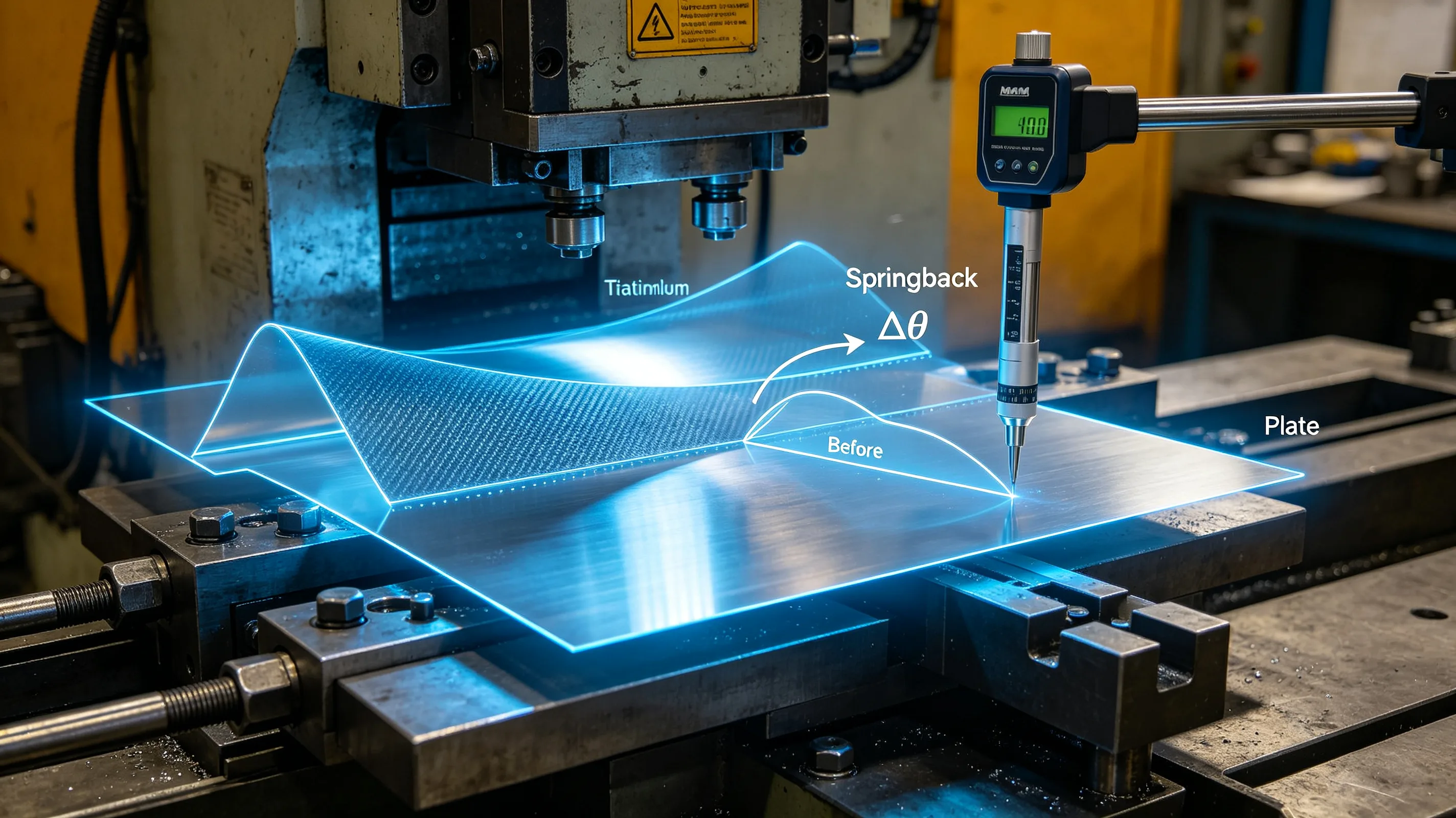
Springback in titanium machining is a direct consequence of the material’s low modulus of elasticity. At roughly 50 percent of steel’s stiffness, titanium features deflect more under cutting forces, and they recover more of that deflection when the tool passes. Managing springback is essential for holding tight tolerances on thin-wall and precision-machined titanium components. The broader topic of dimensional stability, including thermal and residual stress effects, is covered in the article on titanium deformation causes and prevention.
Why springback occurs and where it matters most
Titanium’s modulus of elasticity ranges from 105 to 115 GPa, compared to approximately 200 GPa for steel. This means that under an equivalent cutting force, a titanium feature will deflect nearly twice as much as a steel feature of the same geometry. When the tool passes and the cutting force is removed, the deflected material springs back toward its original position. If the CAM program does not account for this springback, the machined dimension will differ from the programmed dimension.
Springback matters most in three specific situations. The first is thin-wall machining, where the wall height is large relative to its thickness and the wall deflects significantly under even moderate cutting forces. The second is precision boring and turning of thin-wall rings and housings, where the part deflects under clamping and cutting forces and recovers after the tool passes. The third is hole machining in thin-wall sections, where the wall deflection during drilling or boring produces non-round holes that spring back to a different diameter after the tool exits.
How springback interacts with cutting forces
The magnitude of springback depends on the cutting force and the local stiffness of the feature being machined. Cutting force is a function of material removal rate, tool sharpness, and tool geometry. Local stiffness is a function of wall thickness, wall height, and the support provided by the surrounding structure. Both factors change continuously during machining.
In thin-wall pocket milling, the springback is largest at the top of the wall, where the wall is unsupported and deflects the most. As the tool moves down the wall, the springback decreases because the lower portion of the wall is supported by the floor of the pocket. The variability of springback along the wall height means that a single compensation value applied across the entire surface will overcompensate in some areas and undercompensate in others.
Tool wear increases springback indirectly. A worn tool generates higher cutting forces, which produce greater deflection and greater springback. A tool that produced acceptable dimensions at the start of its life may begin to produce oversize features as it wears, even though the tool itself has not changed geometry enough to affect the theoretical cutting path. This force-driven dimensional drift is one reason why tool change intervals based on flank wear limits are sometimes insufficient for tight-tolerance titanium features.
CAM compensation approaches for springback
The most common compensation method is to offset the toolpath by an estimated springback value. For a thin wall that deflects by 0.05 mm under cutting forces, the toolpath is shifted by 0.05 mm so that the tool cuts deeper, and the wall springs back to the intended dimension. This approach works when the springback is consistent across the feature and stable over the production run.
For features where springback varies along the toolpath, tapered compensation values can be applied. The CAM program is set up with a variable offset that is largest at the top of the wall and decreases toward the bottom, matching the deflection profile. This requires an accurate model of how the wall deflects under cutting forces, which can be developed from empirical measurements or finite element analysis.
Adaptive machining uses in-process measurement to adjust the toolpath in real time. A probe or laser measurement system measures the feature after a roughing pass, calculates the actual springback, and adjusts the finishing toolpath to match. This approach compensates for part-to-part variation in material properties, fixture stiffness, and thermal conditions, but it requires machine tools with probing capability and control systems that can accept dynamic toolpath adjustments.
Fixturing strategies that reduce springback
The most effective way to manage springback is to reduce it at the source by supporting the workpiece more rigidly. Hydraulic or pneumatic fixtures that apply uniform support across thin-wall features reduce deflection under cutting forces and produce more consistent springback behavior.
For thin-wall rings and tubular components, expanding mandrels that support the part from the inside eliminate the springback from clamping deformation. The part is supported uniformly around its circumference, and the cutting forces are distributed across a larger area. The springback that remains after machining is primarily from the cutting forces themselves rather than from clamping distortion.
In pocket machining, leaving strategic support ribs that are removed in a separate operation can stabilize thin walls during roughing and semi-finishing. The support ribs are machined away in the final finishing pass, and the springback at that point is minimal because the finishing pass removes very little material with low cutting forces.
Table 1: Springback magnitude in thin-wall titanium (typical values for 2.0 mm wall)
| Wall height | Deflection under finish cut | Springback after tool passes | Compensation needed |
|---|---|---|---|
| 10 mm | 0.01–0.02 mm | 0.008–0.015 mm | Minimal |
| 20 mm | 0.03–0.05 mm | 0.025–0.04 mm | Moderate |
| 30 mm | 0.08–0.12 mm | 0.06–0.10 mm | Significant |
| 40 mm | 0.15–0.25 mm | 0.12–0.20 mm | Major |
For thin-wall and precision titanium features where springback compensation is critical, request a process study and our 5-axis titanium machining services will validate the CAM compensation strategy for your geometry.