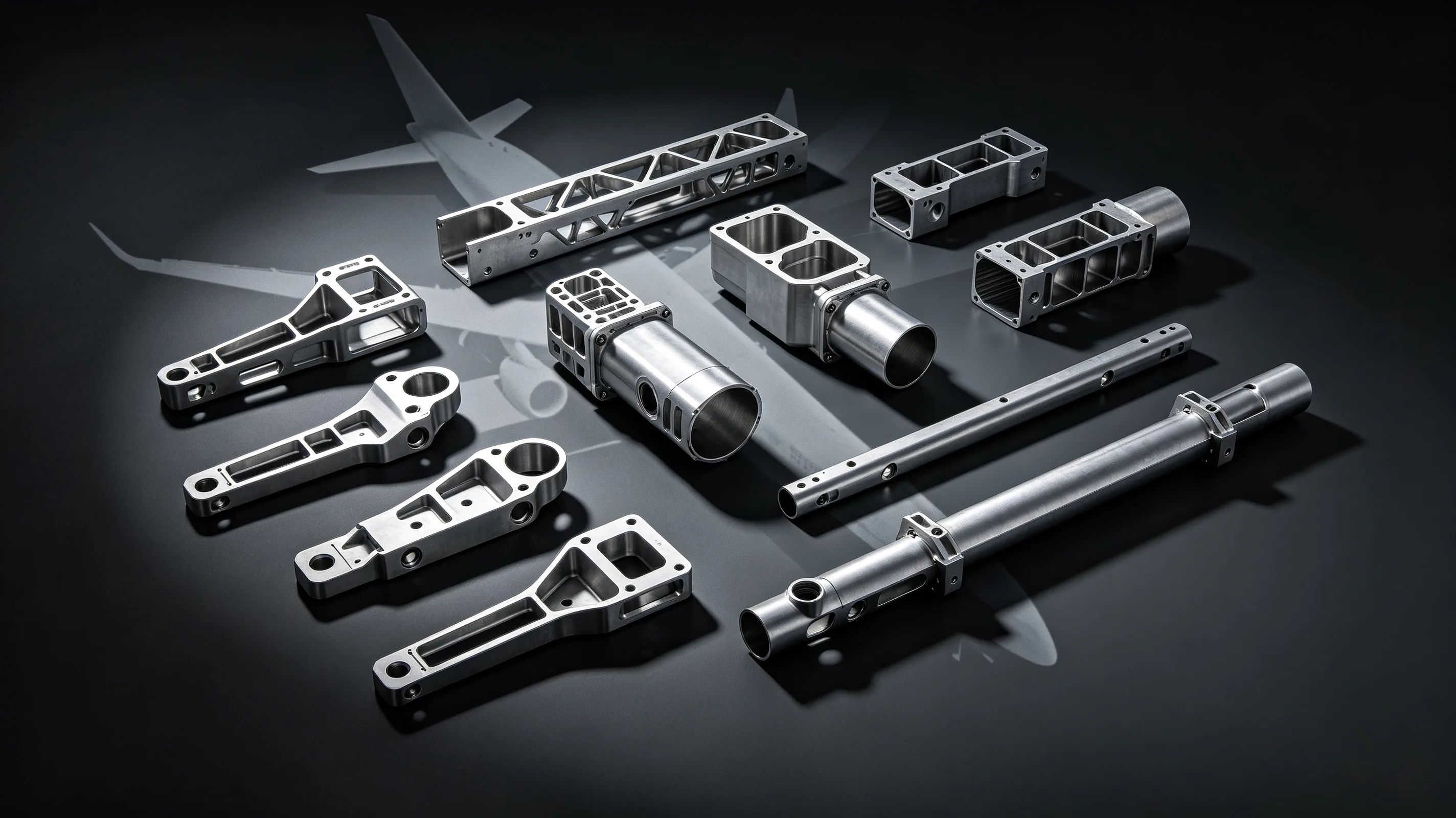
Aerospace titanium components present a convergence of manufacturing challenges that are rarely encountered together in other industries. The materials are difficult to machine, the geometries are complex with thin walls and deep pockets, the tolerances are tight, and the traceability and documentation requirements are extensive. Understanding how these factors interact is important for both design engineers who specify aerospace titanium components and procurement teams who select suppliers for them.
Thin-wall structural challenges
Aerospace structural components — bulkheads, frames, ribs, and fittings — are typically designed with thin walls to minimize weight. Wall thicknesses of 1.0 to 2.0 mm are common, with aspect ratios ranging from 10 to 1 to 15 to 1. These thin walls deflect under cutting forces, and the deflection must be managed through toolpath strategy, fixturing, and pass sequencing. Detailed guidelines for thin-wall machining are covered in the thin wall titanium machining guide, and the design constraints are discussed in the titanium CNC design guide.
The high material removal ratios typical of aerospace structural components — often 80 to 90 percent of the starting stock is machined away — create residual stress redistribution problems. The stresses locked in the raw plate or forging are released as material is removed, and the part can distort significantly if the machining sequence is not designed to manage stress redistribution. Stress-relieved raw material and symmetrical material removal sequences are standard practice.
Tight tolerance requirements
Aerospace titanium components typically have tolerance requirements of ±0.05 to ±0.10 mm for structural features, with some locating features and mating surfaces specified at ±0.025 mm. These tolerances must be maintained across large components that can be 500 mm or more in length, where thermal expansion alone can account for a significant fraction of the tolerance budget. The titanium CNC tolerance guide provides detailed capability data by feature type.
The thermal stability of the machine tool and workpiece over the machining cycle is a primary concern for large aerospace components. A component that is roughed and finished in the same setup on a machine without coolant temperature control can experience dimensional drift of 0.02 to 0.05 mm over an eight-hour production cycle due to thermal effects alone.
Material traceability and certification
Aerospace material traceability requirements are extensive. Each titanium component must be traceable to the specific heat of material it was machined from, and the material certification documents — mill test reports documenting chemical composition and mechanical properties — must be retained for the life of the program plus a specified retention period.
The traceability system extends beyond the raw material to include process parameters, inspection results, and any non-conformances. For critical flight safety components, the traceability records can include several hundred pages of documentation for a single production lot. The supplier’s ability to manage this documentation is as important as their ability to machine the component to print.
Surface integrity requirements
Aerospace surface integrity requirements go beyond geometric roughness. The surface must be free of alpha case, burning, smearing, and embedded contaminants. Inspection at 50x to 200x magnification is typically required to verify surface condition.
The surface integrity requirements influence machining parameters. Cutting speeds must be selected to avoid thermal damage to the surface. Tool change intervals must be conservative enough that worn tools do not generate surface defects. Coolant concentration and condition must be maintained within the specified range to provide consistent lubrication and cooling at the cutting interface.
Process control for AS9100D compliance
Production of aerospace titanium components under AS9100D requires documented process control at every stage. The process specification — a document that defines the machining sequence, tooling, parameters, and inspection points — must be approved before production begins. Any deviation from the approved process requires documented justification and customer approval.
The process specification typically includes the cutting tools, speeds and feeds, coolant type and pressure, inspection frequency and methods, and acceptance criteria for each feature. The specification is developed during the process qualification phase and becomes the controlling document for production. Changes to the process — even those that improve efficiency — must be evaluated for their effect on part quality before implementation.
In-process inspection is required at defined stages, typically after roughing, after semi-finishing, and after finishing. The inspection results are documented and retained as part of the component’s quality record. First article inspection, which verifies that the production process produces parts that meet all drawing requirements, is performed at the start of production and after any significant process change.
For aerospace titanium components with demanding tolerance and traceability requirements, submit your RFQ and our engineers will review the process specification and inspection plan for your program.
Table 1: Aerospace titanium component manufacturing considerations
| Requirement | Typical specification | Process implication |
|---|---|---|
| Wall thickness | 1.0–0.0 mm | Toolpath strategy, multiple semi-finishing passes |
| Tolerance | ±0.05–0.10 mm standard; ±0.025 mm critical | Thermal management, in-process probing |
| Material removal ratio | 80–0% | Stress-relieved stock, balanced material removal |
| Surface integrity | No alpha case, burning, smearing | Conservative speeds, tool change intervals |
| Traceability | Heat number to finished component | Documentation system, record retention |
| Process control | AS9100D compliant | Approved process specification, in-process inspection |