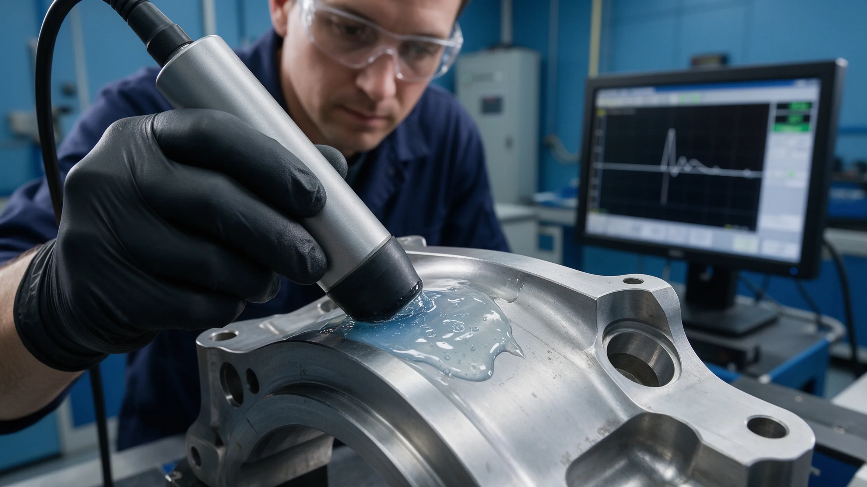
Non-destructive testing (NDT) is the set of inspection methods that detect defects in titanium parts without damaging the part. For titanium aerospace, medical, and chemical processing parts, NDT is the safety net that catches the defects that visual and dimensional inspection miss — subsurface cracks, inclusions, porosity, lack of fusion in welds, and other volumetric defects that the eye cannot see and the CMM cannot measure. The cost of an undetected defect is typically a service failure, an in-service crack, a leak, or a fracture, and the cost of NDT is typically 1–5% of the part cost. The procurement decision is which NDT method to specify, on which parts, at what sensitivity, and to what acceptance threshold.
This article works through the four procurement decisions that determine whether an NDT spec is correctly specified: defect types to detect, NDT method selection, acceptance thresholds, and the integration with the FAI and the production inspection. It assumes the AS9102 FAI article, the MTR field-by-field guide, and the tolerance cost article as background — those cover the broader quality and tolerance landscape; here we focus on the NDT process specifically. For the supplier qualification side, the AS9100 qualification guide is the cross-reference.
- Why NDT is required for titanium parts
- The defect taxonomy: what NDT is looking for
- NDT method comparison: UT, X-ray, PT, ET, and emerging methods
- Method selection by defect type and part geometry
- Acceptance thresholds and standards
- NDT integration with the FAI and the production inspection
- NDT checklist
Why NDT is required for titanium parts
NDT is required for titanium parts in three application categories: aerospace structural parts where undetected defects can cause catastrophic in-service failure, medical implants where defects can cause patient harm, and chemical processing pressure-containing parts where defects can cause leaks. The visual and dimensional inspection methods covered in the FAI article catch surface defects and dimensional errors, but they do not catch subsurface defects. NDT fills that gap.
The defect types that NDT catches but visual and dimensional inspection miss:
- Subsurface cracks. Cracks below the machined surface, typically 0.5–5 mm below the surface, that are not visible on the surface and not detectable by dimensional measurement. Subsurface cracks are typically caused by residual stress redistribution (covered in the stress relief article), by work-hardening from machining, or by hydrogen embrittlement (covered in the PEM electrolyzer article).
- Inclusions. Foreign material embedded in the part, typically from the mill (tungsten from the machining, ceramic from the cutting tool, or metallic inclusion from the original ingot). Inclusions are typically 0.1–2 mm in size and can be at any depth in the part.
- Porosity. Void in the part, typically from the original ingot (shrinkage porosity, gas porosity) or from the welding process (lack of fusion, lack of penetration). Porosity is typically 0.1–5 mm in size and can be at any depth.
- Lack of bond (in clad or welded parts). A region where the bond between two layers or two pieces of titanium is incomplete or absent. Lack of bond is typically 1–20 mm in size and is at the interface between the two pieces.
- Surface-breaking cracks that are not visible. Cracks that are open at the surface but are not visible to the eye, typically because the crack is closed (no gap), is oriented parallel to the surface, or is filled with machining debris.
The cost of NDT is small relative to the cost of an undetected defect. A typical NDT inspection (ultrasonic or X-ray) on a titanium aerospace part is 500 per part, or 1–5% of the part cost. The cost of an undetected defect — a service failure, a recall, a litigation — is typically 10,000,000, depending on the part and the application. The NDT cost-benefit ratio is typically 100:1 to 100,000:1, and the procurement decision is to specify the right NDT method, at the right sensitivity, on the right parts.
The defect taxonomy: what NDT is looking for
The defect taxonomy is the classification of the defects that NDT is looking for. The taxonomy is the basis for the NDT method selection (different methods are sensitive to different defects) and the acceptance threshold (different applications have different criticality for the same defect). The standard taxonomy per ASTM E1316 and EN 1330-1:
- Cracks. Linear, planar defects with sharp tips. The most severe defect type, and the primary driver of NDT requirement for fatigue-critical parts.
- Porosity. Volumetric, rounded defects with no sharp tips. The most common defect in castings and welds.
- Inclusions. Volumetric, foreign-material defects. The dominant defect in forgings.
- Lack of bond / lack of fusion. Planar, interface defects in clad or welded parts.
- Surface defects (scratches, gouges, pits). Surface-breaking defects that are visible to the eye (typically > 0.5 mm in size) or detectable by PT or ET.
The defect criticality is the severity of the defect in the specific application. A 0.5 mm crack is critical in an aerospace fatigue part (the crack is a fatigue initiation site) but is non-critical in a chemical processing pressure vessel (the crack does not propagate under the static load). The acceptance threshold for a given defect type is set by the application’s criticality, and the procurement spec should reference the application’s criticality class (typically per ASME BPVC Section V for pressure vessels, per ASTM F3091 for medical implants, or per AMS 2370 for aerospace).
NDT method comparison: UT, X-ray, PT, ET, and emerging methods
The five NDT methods applicable to titanium parts, with the principle, the defect types detected, the sensitivity, the surface requirement, the cycle time, and the cost per inspection:
Ultrasonic Testing (UT). High-frequency sound waves (typically 1–25 MHz) are transmitted into the part through a coupling medium (water, gel, or air). The waves reflect off internal defects and off the back wall, and the reflected signals are displayed on a screen or recorded digitally. UT detects volumetric defects (porosity, inclusions) and planar defects (cracks, lack of bond) at any depth, with the minimum detectable defect size of roughly 0.5 mm at depths of 10–100 mm. UT requires a smooth surface for the transducer to couple, and the surface must be accessible to the transducer. UT cycle time is 5–30 minutes per part, and the cost is 500 per part for a typical titanium aerospace part.
Radiographic Testing (X-ray or CT). X-rays (typically 50–500 keV) are passed through the part, and the absorption is recorded on a film or a digital detector. X-ray detects volumetric defects (porosity, inclusions) with the minimum detectable defect size of roughly 1–2% of the part thickness. CT scanning produces a 3D image of the part, with the minimum detectable defect size of roughly 0.1–0.5 mm at any depth, but the cost is 5–10× the cost of conventional X-ray. X-ray requires access to both sides of the part, and the cycle time is 5–20 minutes per part. The cost is 300 per part for conventional X-ray, 5,000 per part for CT.
Penetrant Testing (PT). A liquid penetrant is applied to the surface, allowed to dwell (typically 10–30 minutes), and then removed. A developer is applied, which draws the penetrant out of any surface-breaking defects. PT detects surface-breaking defects (cracks, porosity open to the surface, lack of bond open to the surface) with the minimum detectable defect size of roughly 0.1–0.5 mm at the surface. PT requires a clean surface, and the cycle time is 30–60 minutes per part. The cost is 200 per part for a typical titanium part.
Eddy Current Testing (ET). An alternating-current coil is placed near the surface, and the eddy currents induced in the part are measured. ET detects surface and near-surface defects (cracks, porosity) with the minimum detectable defect size of roughly 0.1–0.5 mm at depths of 0–3 mm. ET requires a smooth surface and access to the surface, and the cycle time is 1–5 minutes per part. The cost is 200 per part for a typical titanium part.
Computed Tomography (CT). A 3D extension of X-ray, with the part rotated in the X-ray beam and the absorption recorded at multiple angles. CT produces a 3D image of the part with the minimum detectable defect size of roughly 0.1–0.5 mm at any depth. CT is the most sensitive method for volumetric defects, but the cost is 5–10× the cost of conventional X-ray. CT is typically reserved for safety-critical parts.
The method selection is driven by the defect type, the defect location, the surface condition, and the part geometry. The matrix below summarises the method selection.
| Defect type | Best method | Secondary method | Sensitivity | Surface requirement |
|---|---|---|---|---|
| Subsurface crack (0.5–5 mm depth) | UT | X-ray | 0.5 mm at 10–100 mm depth | Smooth, accessible |
| Surface-breaking crack | PT or ET | UT (surface wave) | 0.1–0.5 mm | Clean, accessible |
| Porosity (volumetric) | X-ray or CT | UT | 1–2% of thickness (X-ray), 0.1–0.5 mm (CT) | Any |
| Inclusions (volumetric) | X-ray or CT | UT | 1–2% of thickness (X-ray), 0.1–0.5 mm (CT) | Any |
| Lack of bond (interface) | UT | X-ray | 0.5–2 mm at the interface | Smooth, accessible |
| Surface defects (visible) | Visual | PT or ET | 0.5 mm (visual), 0.1–0.5 mm (PT/ET) | Clean, accessible |
Method selection by defect type and part geometry
The method selection is a function of the defect type (which NDT method is sensitive to the defect), the defect location (surface vs. subsurface, near-surface vs. deep), and the part geometry (the accessibility of the surface to the NDT transducer or probe). The selection rules:
Subsurface defects (cracks, porosity, inclusions, lack of bond). UT is the standard for subsurface defects in titanium. UT detects defects at depths of 10–100 mm with a sensitivity of 0.5 mm, and the cycle time is 5–30 minutes per part. UT is the right choice for fatigue-critical aerospace parts, medical implants, and pressure-containing chemical processing parts. X-ray or CT is the alternative for parts where the geometry does not allow UT access (e.g., complex internal features).
Surface-breaking defects (cracks, porosity open to the surface, lack of bond open to the surface). PT or ET is the standard for surface-breaking defects. PT detects defects at the surface with a sensitivity of 0.1–0.5 mm, and the cycle time is 30–60 minutes per part. ET is the alternative for parts where PT is not practical (e.g., parts that cannot be cleaned thoroughly, or parts with complex surface geometry that traps penetrant). PT and ET are typically used together — PT for the surface-breaking defect detection, ET for the near-surface defect detection (depths of 0–3 mm).
Volumetric defects in complex geometry. X-ray or CT is the standard for volumetric defects in parts where UT and PT/ET are not practical. X-ray is the lower-cost option, with a sensitivity of 1–2% of the part thickness. CT is the higher-sensitivity option, with a sensitivity of 0.1–0.5 mm at any depth. CT is typically reserved for safety-critical parts where the higher sensitivity justifies the higher cost.
Welded fabrications. Welds require a combination of methods. UT is the standard for weld inspection, with the probe scanning along the weld and the adjacent heat-affected zone. PT is used for the surface-breaking defects at the weld cap and root. X-ray is the alternative for critical welds where the geometry does not allow UT access. The acceptance threshold for welds is typically per ASME BPVC Section IX (for pressure vessels) or AWS D17.1 (for aerospace welds).
The method selection should be documented in the inspection plan, and the inspection plan should be referenced in the FAI report and the process plan.
Acceptance thresholds and standards
The acceptance threshold is the defect size above which the part is rejected. The threshold is set by the application’s criticality and by the relevant standard. The standards that apply to titanium parts are:
- ASME BPVC Section V (Nondestructive Examination) and Section VIII (Pressure Vessels). The standard for chemical processing pressure vessels, with acceptance thresholds per the weld classification and the service condition.
- ASTM E1417 (Liquid Penetrant Examination), ASTM E309 (Eddy Current Examination), ASTM E426 (Electromagnetic Examination). The standards for the specific NDT methods.
- AMS 2370 (Quality Assurance Sampling and Testing), AMS 2371 (Ultrasonic Inspection), AMS 2372 (Penetrant Inspection). The aerospace standards for titanium parts.
- ASTM F3091 (Standard Specification for Surface Cleaning, Finishing, and Marking of Metallic Parts for Surgical Implants). The standard for medical implant NDT.
- EN 10228-1 through EN 10228-4 (Non-destructive testing of forgings). The European standards, applicable to titanium parts in some aerospace and chemical processing programs.
The acceptance thresholds in the standards are typically expressed as:
- Linear indications (cracks, lack of fusion). Maximum length, maximum number per unit area, and maximum spacing. The threshold is typically 1.0–2.0 mm for aerospace structural parts, 0.5–1.0 mm for medical implants, and 2.0–5.0 mm for chemical processing pressure vessels.
- Rounded indications (porosity, inclusions). Maximum diameter, maximum number per unit area, and maximum aggregate length. The threshold is typically 1.0–2.0 mm for aerospace structural parts, 0.5–1.0 mm for medical implants, and 2.0–3.0 mm for chemical processing pressure vessels.
- Lack of bond (in clad or welded parts). Maximum linear dimension, typically 1.0–3.0 mm depending on the application.
The buyer who specifies the acceptance threshold in the inspection plan is the buyer who controls the quality of the parts. The threshold must be specified in writing, with the standard and the threshold value, and the inspection must be performed and documented per the standard.
NDT integration with the FAI and the production inspection
NDT is one of the inspection methods documented in the AS9102 FAI report, and the FAI’s NDT section is the verification that the part is NDT-clean at the first article. The NDT section typically includes:
- The NDT method(s) performed.
- The standard(s) referenced (ASME BPVC, ASTM, AMS, EN).
- The acceptance threshold(s) applied.
- The inspection result (pass / fail, with the defect indications documented).
- The inspector’s signature and the inspection date.
- The calibration records for the NDT equipment (UT probe, X-ray source, PT penetrant, ET coil).
The NDT integration with the FAI is the verification that the part is NDT-clean at the start of the production run. The NDT integration with the production inspection is the verification that the part is NDT-clean throughout the production run. The typical production inspection is a sampling plan (typically 10–20% of the lot for safety-critical parts, 1–5% for general parts) with a partial NDT on the sampled parts. The sampling rate is documented in the inspection plan, and the NDT result is documented in the per-lot quality record.
A buyer who specifies NDT on the FAI but not on the production inspection accepts the risk that the production run produces a defect that the FAI did not catch. A buyer who specifies NDT on both the FAI and the production inspection accepts the cost of the production NDT (typically 1–3% of the part cost) in exchange for the reduced risk of a service failure. The trade-off is application-specific, and the procurement decision is to specify the NDT scope and the sampling rate that match the application’s criticality.
NDT checklist
- Specify the NDT method(s) on the print or in the inspection plan (UT, X-ray, PT, ET, CT, or a combination).
- Reference the standard(s) for each NDT method (ASME BPVC, ASTM, AMS, EN).
- Specify the acceptance threshold(s) for each defect type (crack, porosity, inclusion, lack of bond, surface defect), with the threshold value and the standard reference.
- Specify the inspection scope (FAI only, FAI + per-lot sampling, 100% on every part) and the sampling rate.
- Document the NDT equipment calibration records and the inspector qualifications (per NAS 410 or ISO 9712).
- Verify the NDT result on the FAI before the production run is released.
- Track the NDT acceptance rate and the time-to-inspection, and use the data to drive process improvements.
- For welded fabrications, specify the weld inspection scope per ASME BPVC Section IX or AWS D17.1.
- For medical implants, specify the NDT scope per ASTM F3091 or ISO 13485.
- For chemical processing pressure vessels, specify the NDT scope per ASME BPVC Section V.
- For aerospace structural parts, specify the NDT scope per AMS 2370 / AMS 2371 / AMS 2372.
For an NDT review against a specific titanium program, send the print, the inspection plan, and the application to the RFQ intake; the engineering team returns a manufacturability feedback with NDT method, acceptance threshold, and inspection scope recommendations. The 5-axis titanium machining services and engineering review capability at Boze review every titanium NDT program against the checklist above before the buyer’s submission, and the typical outcome is a review that surfaces 1–2 NDT-scope gaps per program. For Ti-6Al-4V Grade 5 parts in particular, the NDT method and the acceptance threshold are what determine whether a defect is caught at the FAI or at the service failure — and that determination is what drives the buyer’s total cost of ownership over the program.