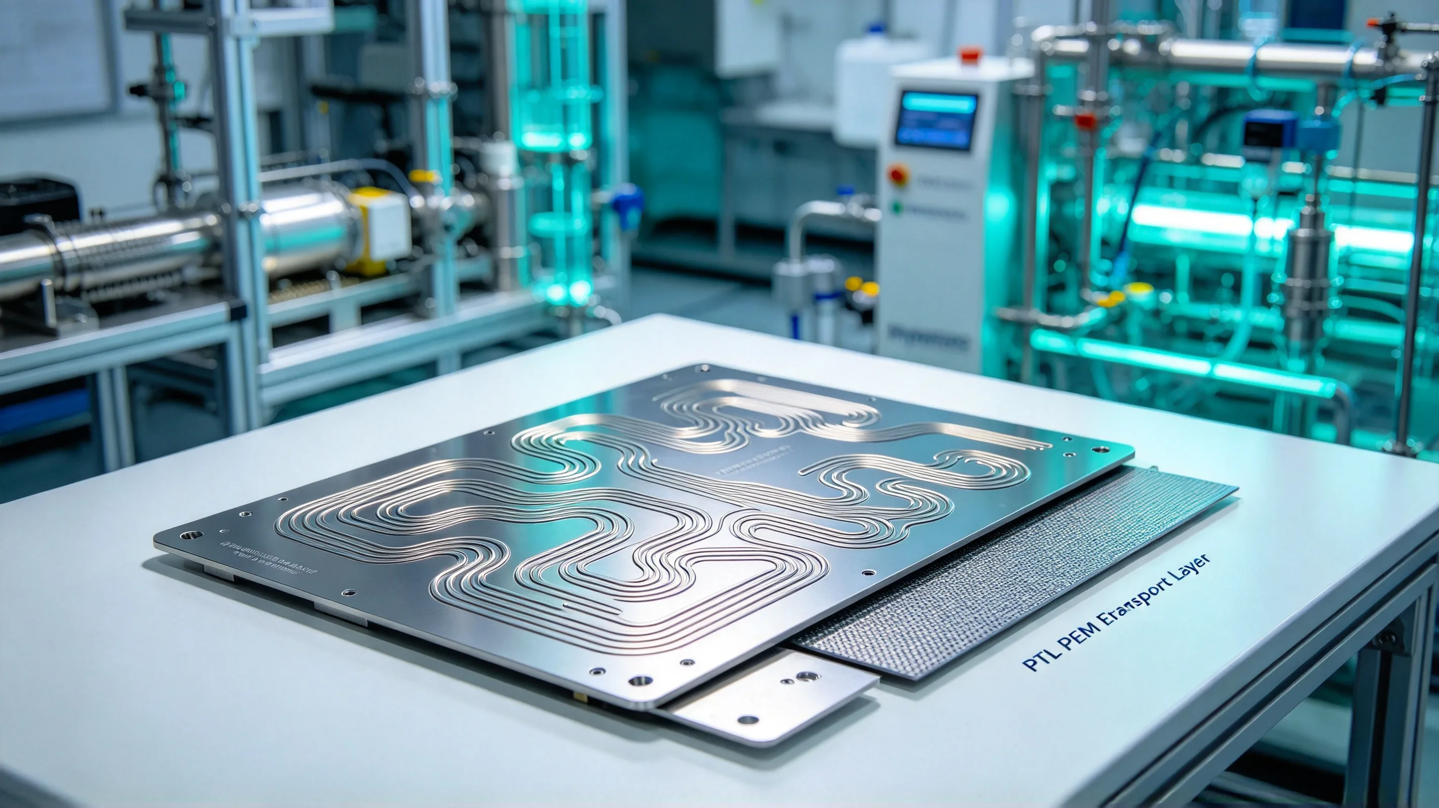
The PEM (Proton Exchange Membrane) electrolyzer is the workhorse technology for green hydrogen production from renewable electricity, and titanium is the structural material of choice for the stack components that face the harsh anode-side environment. The anode side of a PEM cell operates at pH 1–3, with dissolved oxygen, high anodic potentials (1.5–2.5 V vs SHE), and temperatures of 60–80 °C — an environment that would dissolve stainless steel in hours but that titanium handles for 50,000+ hours of operation. The CNC-machined titanium components in a PEM stack — the bipolar plates, the porous transport layer substrates, the current collector frames, and the end plate components — are the parts that determine the stack’s power density, efficiency, and service life.
This article works through the four procurement decisions that determine whether a titanium PEM electrolyzer component is correctly specified: material grade selection for the anode environment, the machining requirements for the bipolar plate flow field, the hydrogen embrittlement risk on the cathode side, and the procurement specifications for the stack supplier. It assumes the chemical processing parts article and the grade selection guide as background — those cover the broader chemical processing and grade landscape; here we focus on the PEM electrolyzer application. For the general procurement process, the RFQ checklist is the cross-reference.
- Why titanium is the material of choice for PEM electrolyzers
- The PEM stack components that are CNC machined
- Grade selection for the anode and cathode environments
- Bipolar plate machining: flow field, lands, and channels
- Hydrogen embrittlement and the cathode-side material concern
- Surface treatment: precious metal coatings and passivation
- Procurement specifications for PEM electrolyzer components
- PEM electrolyzer components checklist
Why titanium is the material of choice for PEM electrolyzers
The PEM electrolyzer cell has two distinct environments that demand two different material strategies:
Anode side (oxygen evolution reaction, OER). The anode operates at pH 1–3 (the membrane is in contact with a proton-rich environment), with high anodic potentials (1.5–2.5 V vs SHE), temperatures of 60–80 °C, and dissolved oxygen. In this environment, titanium forms a stable, conductive TiO₂ passive film that supports the OER reaction without corrosion. The passive film is the same film that protects titanium in the chemical processing environment (covered in the chemical processing article), and the same isocorrosion data applies. Stainless steel and nickel-based alloys do not survive this environment — they dissolve within hours, contaminating the membrane and the catalyst. Titanium is the only commercially available structural material that holds up.
Cathode side (hydrogen evolution reaction, HER). The cathode operates at a near-neutral pH (the membrane side is acidic, the cathode side is proton-depleted), with cathodic potentials (0 to -0.5 V vs SHE), temperatures of 60–80 °C, and dissolved hydrogen. In this environment, the titanium oxide film is reduced to a less-protective form, and the titanium surface is in contact with nascent hydrogen that can absorb into the metal. The hydrogen embrittlement risk on CP titanium is real but manageable; on Ti-6Al-4V and other alpha-beta alloys, the risk is much higher and has been the subject of significant industry attention. The standard mitigation is CP titanium on both sides of the cell, with the cathode-side CP grade selected for hydrogen compatibility rather than for strength.
The PEM stack architecture (per-cell bipolar plate, membrane electrode assembly, porous transport layer, current collector) places titanium in three roles: the structural frame (bipolar plate), the substrate for the catalyst-coated porous transport layer, and the current collector / land region between the cells. All three roles require the same combination of corrosion resistance, machinability, and cost that CP Grade 1 or Grade 2 provides.
The PEM stack components that are CNC machined
The titanium content of a PEM stack is concentrated in a small number of components, each with its own machining demand and its own procurement specification.
Bipolar plates (BPPs). The largest titanium content in a PEM stack, and the most demanding machining. A typical BPP is a 200–400 mm × 200–400 mm titanium plate, 0.5–2.0 mm thick, with a serpentine or interdigitated flow field machined into the active area (typically 100–300 cm²) and a perimeter manifold for the water and gas ports. The flow field is machined as a series of parallel channels (typically 0.5–1.0 mm wide, 0.3–0.8 mm deep) separated by lands (typically 0.5–1.0 mm wide). The machining demand is high — the channels must be sharp at the bottom, with no burrs, and the land-to-channel tolerance must be held to ±0.05 mm or tighter. The standard material is CP Grade 1 (for formability in thin sections) or CP Grade 2 (for general use). Some designs use Grade 7 for the most demanding service.
Porous transport layer (PTL) substrate. The PTL is the porous layer that distributes water to the anode catalyst and removes the oxygen gas produced. In commercial PEM cells, the PTL is typically a sintered titanium powder layer on a titanium substrate, or a titanium felt / mesh structure. The substrate (the part that the sintered powder or felt is bonded to) is CNC machined from thin titanium sheet (typically 0.2–0.5 mm) or foil. The machining demand is moderate — the substrate is a flat plate with ports and a perimeter feature. CP Grade 1 or Grade 2 is standard.
Current collector frames. The frames that hold the membrane electrode assembly and provide the electrical contact between the cells. The current collector is typically a CNC-machined titanium frame with a gold or platinum coating on the contact area (to minimise the contact resistance). The machining demand is moderate — flat or formed plate with ports, perimeter features, and contact lands. CP Grade 2 is standard.
End plates and tie rods. The structural components that hold the stack together against the clamping force. The end plates are typically CNC-machined from thicker titanium plate (5–25 mm), and the tie rods are titanium bars with rolled threads. The machining demand is low to moderate. CP Grade 2 or Grade 4 is standard (Grade 4 for the higher-strength tie rods).
Manifolds and port fittings. The water and gas distribution components. CNC-machined from bar or plate, with port connections that match the stack’s flow field. The machining demand is low to moderate. CP Grade 2 is standard.
Grade selection for the anode and cathode environments
The grade selection for PEM electrolyzer components is driven by three variables: the side of the cell (anode vs cathode), the operating conditions (pH, potential, temperature), and the mechanical requirement (strength vs formability vs hydrogen compatibility).
| Component | Side of cell | Recommended grade | Rationale |
|---|---|---|---|
| Bipolar plate (active area) | Anode | CP Grade 1 or CP Grade 2 | Corrosion resistance in OER; formability for thin sections |
| Bipolar plate (frame) | Anode / structural | CP Grade 2 | General-purpose, balance of formability and strength |
| PTL substrate | Anode | CP Grade 1 | Formability in thin sections (0.2–0.5 mm) |
| Current collector frame | Anode | CP Grade 2 | General-purpose |
| Cathode-side flow field | Cathode | CP Grade 1 or CP Grade 2 | Hydrogen compatibility; avoid alpha-beta alloys |
| End plate | Structural | CP Grade 2 or Grade 4 | Strength |
| Tie rod | Structural | CP Grade 4 or Grade 9 | Higher strength (UTS > 550 MPa) |
| Manifold / port | Anode / cathode | CP Grade 2 | General-purpose |
The single most important grade rule for PEM components is to avoid Ti-6Al-4V (Grade 5) and other alpha-beta alloys on the cathode side. Alpha-beta alloys are susceptible to hydrogen embrittlement in the cathodic environment, and the embrittlement can lead to cracking and stack failure within the first 1,000–5,000 hours of operation. The standard mitigation is to use CP titanium for the cathode-side flow field and current collector, and to use Grade 9 or higher-strength CP Grade 4 for the tie rods (which are not in direct contact with the membrane-side environment).
Grade 7 is occasionally specified for the anode-side bipolar plate in the most demanding service (high anodic potential, high temperature), where the palladium addition improves the corrosion margin. The cost premium (2–3× the material cost of CP Grade 2) is recovered by the longer service life and the reduced maintenance cycle. The buyer should specify Grade 7 only when the operating conditions exceed the CP Grade 2 envelope (typically 1.8 V vs SHE, 70 °C, pH < 1.5), not as a default.
Bipolar plate machining: flow field, lands, and channels
The bipolar plate is the most demanding machining job in the PEM stack, and the machining requirements are different from any other titanium application covered in this blog. The flow field geometry is the dominant feature, and the flow field is the source of most of the manufacturing cost.
The flow field is a serpentine or interdigitated pattern of channels and lands. The channel dimensions are typically 0.5–1.0 mm wide, 0.3–0.8 mm deep, with land widths of 0.5–1.0 mm. The channel depth tolerance is ±0.05 mm or tighter, the land-to-channel edge radius must be < 0.1 mm, and the channel bottom must be smooth and free of burrs (a burr on the channel bottom can puncture the membrane and cause a cell failure).
The machining strategy for the flow field is typically:
- For thin BPPs (0.5–1.0 mm thick): photo-chemical etching is the dominant process, with CNC milling used for the perimeter and port features. Etched BPPs are produced in large panels and separated after etching.
- For medium BPPs (1.0–2.0 mm thick): CNC milling with ball-end mills or form tools, with the flow field machined as a single-pass operation across the active area.
- For thick BPPs (2.0 mm and above): CNC milling with multiple passes, with the flow field machined at a higher feed and a final pass at a lower feed for the surface finish.
The milling tool for the flow field is typically a 0.5–1.0 mm diameter ball-end mill or a form tool, with the cutting parameters tuned for the thin section. Standard milling parameters for titanium (Vc 50–80 m/min, fn 0.05–0.15 mm/rev) are too aggressive for the thin-section BPP — the part deflects, the tool breaks, or the land-to-channel tolerance is missed. The recommended starting parameters for BPP milling are Vc 30–50 m/min, fn 0.03–0.08 mm/rev, with high-pressure coolant (per the drilling guide and the machining processes guide) and a sharp, single-flute tool.
The burr on the channel edges is the most common BPP defect. The burr is typically on the exit side of the channel (the side where the tool exits the channel), and it can be removed by light hand-deburring, by a controlled tumbling operation, or by an electrochemical deburring process. The burr is critical because it can damage the membrane on assembly, and a single BPP with a membrane-damaging burr can fail a stack of 100+ cells.
Hydrogen embrittlement and the cathode-side material concern
Hydrogen embrittlement is the dominant material risk on the cathode side of a PEM cell. The mechanism: nascent hydrogen produced by the HER reaction absorbs into the titanium surface, and the absorbed hydrogen migrates to the stress concentrators (notches, sharp corners, residual stress from machining) where it can cause hydride formation and cracking. The cracking is most severe at high stress (tie rod threads, current collector contact points) and at moderate temperature (60–80 °C is in the worst range for hydride formation in alpha titanium).
The mitigations are:
- Use CP titanium on the cathode side (Grade 1, 2, or 4), not alpha-beta alloys (Grade 5, Grade 9). CP titanium has a higher tolerance for absorbed hydrogen than alpha-beta alloys, and the embrittlement is slower.
- Avoid stress concentrators on the cathode-side components. The flow field edges, the port edges, and the thread roots should be specified with a minimum radius (typically 0.5 mm or larger) to reduce the stress concentration.
- Stress-relieve the cathode-side components after machining (per the stress-relief article). The standard cycle is 540 °C ± 15 °C for 1 hour per inch of thickness, with slow cool under inert atmosphere. The stress relief reduces the residual tensile stress that drives hydrogen embrittlement cracking.
- Specify a bake-out cycle before stack assembly (typically 80–120 °C for 4–8 hours under vacuum). The bake-out removes absorbed hydrogen from the surface and reduces the embrittlement risk on first operation.
- Use Grade 9 or higher-strength CP Grade 4 for the tie rods — these are alpha or near-alpha alloys with higher hydrogen tolerance than alpha-beta alloys. The strength is sufficient for the tie rod application.
The buyer should specify the grade and the post-machining heat treatment for any cathode-side component, and the specification should be reviewed against the operating conditions (pH, potential, temperature, expected service life) before the component is released for production.
Surface treatment: precious metal coatings and passivation
The surface treatment for PEM components is one of three options, depending on the component role and the cost target:
Pickling and passivation (ASTM F86). The standard for all PEM components. Pickling removes the oxide scale and the alpha case from the machined surface; passivation restores the protective oxide film. The process is the same as for chemical processing parts (covered in the chemical processing article). The cost is low and the cycle time is fast (1–2 days). All PEM components should receive at least the pickling and passivation treatment.
Precious metal coating (gold or platinum) on the contact area. The standard for the current collector and the land area of the bipolar plate. The coating reduces the interfacial contact resistance between the titanium and the carbon or graphite component, which improves the cell voltage by 20–50 mV at typical current densities. The coating is applied by physical vapor deposition (PVD), by electroless plating, or by selective brush plating. The cost is moderate to high (the precious metal is a significant line item), and the cycle time is 2–5 days. The specification should include the coating thickness (typically 0.5–5 µm gold, 0.1–1 µm platinum), the coating method, the adhesion test (per ASTM B571), and the electrical resistance target (typically < 5 mΩ·cm² at the contact area).
Catalyst coating on the PTL. The PTL is coated with a precious metal catalyst (typically iridium oxide for the anode, platinum for the cathode) before the membrane electrode assembly is built. The CNC machining of the PTL substrate is followed by a PVD or wet-chemical coating step at a specialist supplier. The supplier’s scope typically includes the substrate machining only, with the coating step handled by the stack integrator.
The procurement spec should specify the surface treatment for each component, with the option to substitute the precious metal coating for a non-coated current collector if the cell voltage target allows. The substitution reduces the per-stack cost by 5–15%, but at the expense of the cell efficiency. The cost-benefit analysis is the buyer’s decision, not the supplier’s.
Procurement specifications for PEM electrolyzer components
The procurement specification for a PEM electrolyzer component has more in common with a semiconductor fab component than with a chemical processing component: high precision, high purity, low tolerance for surface contamination, and a coating spec that drives the cost. The standard documentation package is:
- MTR per EN 10204 3.1 (per the MTR field-by-field guide) with the chemistry and the mechanical properties.
- Dimensional inspection report with all critical features measured (CMM layout for the BPP active area).
- Surface finish report (typically Ra 0.4–0.8 µm on the flow field channels, Ra 0.8–1.6 µm on the perimeter).
- Surface treatment report (pickling / passivation / precious metal coating, with the thickness and the adhesion test result).
- Hydrogen embrittlement test report (per ASTM F1459 or equivalent) for cathode-side components.
- PMI report (per ASTM E1476 or equivalent) for grade verification.
- Process documentation for the stack integrator (flow field drawing with the channel dimensions, the land dimensions, and the manifold port locations).
The PEM industry is moving toward tighter tolerance bands and higher power density, which drives the BPP channel dimensions to 0.3–0.5 mm width and the land widths to 0.3–0.5 mm. The supplier must be able to hold these dimensions consistently, and the procurement spec should include the Cpk target for the channel and land dimensions (typically Cpk ≥ 1.33 for the BPP active area). The CMM total cost of ownership article covers the inspection capacity required for this level of dimensional control.
PEM electrolyzer components checklist
- Specify the grade by ASTM designation (CP Grade 1, CP Grade 2, CP Grade 4) and the form (B265 plate for BPPs, B348 bar for frames and tie rods). Generic “titanium” is not a procurement spec for PEM.
- Avoid Ti-6Al-4V (Grade 5) and other alpha-beta alloys on the cathode side. Use CP titanium for the cathode-side flow field and current collector.
- Specify the surface treatment: pickling + passivation per ASTM F86 for all components; precious metal coating (gold or platinum) for the current collector and the BPP land area.
- Specify the BPP flow field dimensions (channel width, channel depth, land width, edge radius) and the tolerance (±0.05 mm or tighter) on the print.
- Specify the burr-free requirement on the BPP channel edges. A burr on the channel edge can puncture the membrane and fail the stack.
- Specify the post-machining stress relief for cathode-side components (540 °C ± 15 °C for 1 hour per inch, slow cool, inert atmosphere).
- Specify the MTR format (EN 10204 3.1), the dimensional inspection scope (CMM on the BPP active area), and the PMI (per ASTM E1476) at the RFQ stage.
- Specify the hydrogen embrittlement test (per ASTM F1459) for cathode-side components in critical service.
- Specify the channel Cpk target (≥ 1.33 for the BPP active area) and the reporting interval for the Cpk and the scrap rate.
For a PEM electrolyzer components review against a specific stack design, send the STEP file, the operating conditions, the flow field drawing, and the surface treatment spec to the RFQ intake; the engineering team returns a manufacturability feedback with grade, machining, and surface treatment recommendations. The 5-axis titanium machining services and engineering review capability at Boze review every PEM electrolyzer RFQ against the checklist above before any tooling is ordered, and the typical outcome is a review that surfaces 1–2 specification gaps per program. For CP Grade 2 BPPs in particular, the flow field machining and the surface treatment spec are what determine whether the stack meets the power density and efficiency targets — and that determination is what drives the buyer’s levelized cost of hydrogen over the electrolyzer’s service life.