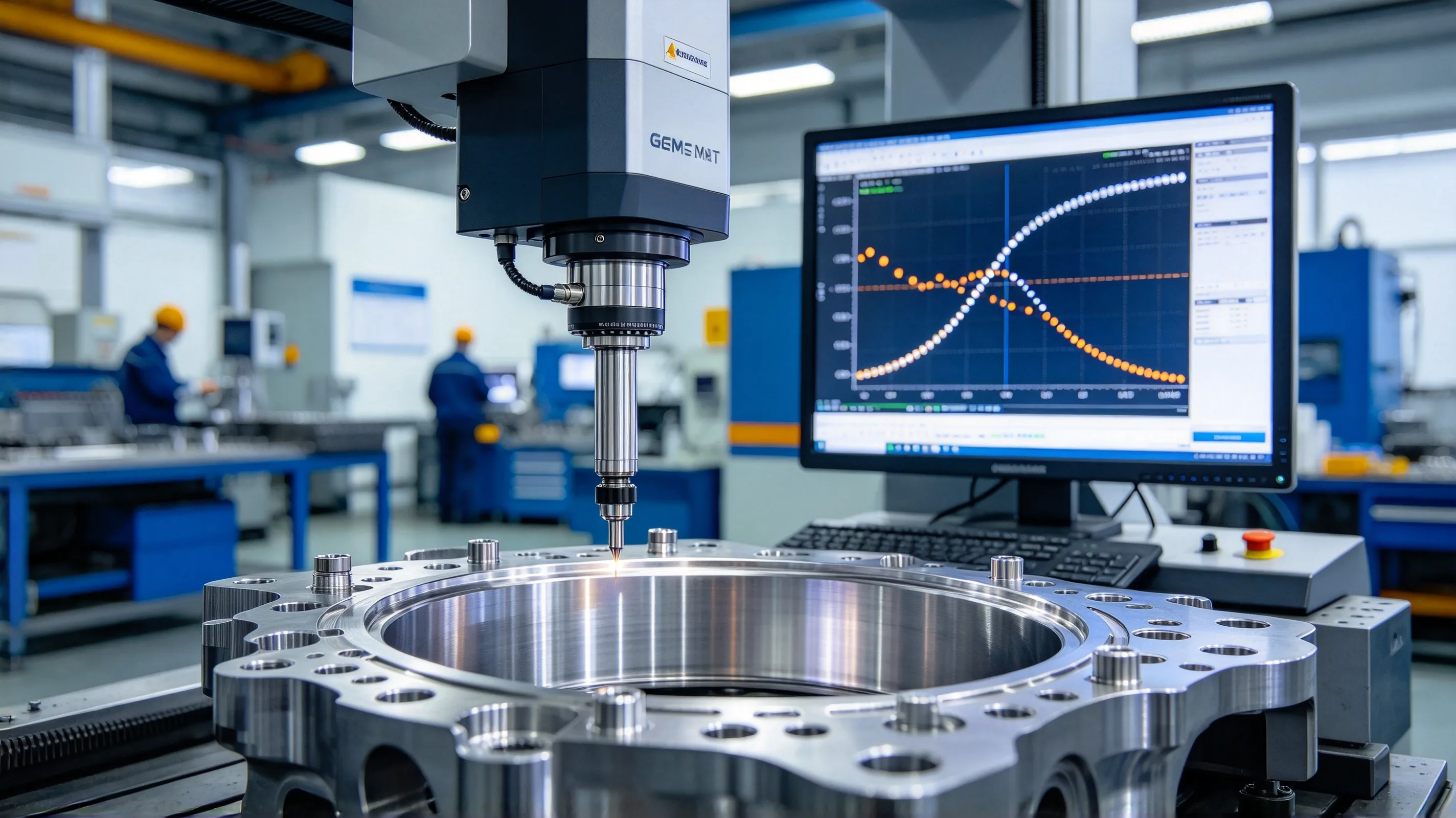
Dimensional drift is the part-to-part variation that appears on a long titanium CNC cycle, even when every other variable is held constant. A part that measures in tolerance on the first article, the tenth article, and the twentieth article can drift out of tolerance by the thirtieth or fortieth article, on a cycle that was producing in-spec parts for the first hour of operation. The drift is the cumulative effect of thermal growth in the machine, tool wear progression, residual stress redistribution as the part is cut free from the stock, and metrology drift in the inspection equipment. The shop that does not have a discipline for detecting and compensating for drift finds the drift in the customer’s incoming inspection, not in the shop’s FAI, and the cost of the drift is the rework, the scrap, and the lost confidence on the next order.
This article works through the four sources of dimensional drift on titanium CNC parts, the compensation methods for each, and the inspection discipline that catches drift before it becomes scrap. It assumes the tolerance cost article and the AS9102 FAI article as background — those cover the tolerance specification and the FAI process; here we focus on the part-to-part variation within a production run. For the workholding side, the workholding article and the deformation prevention article are the cross-references.
- Why dimensional drift is more severe on titanium than on steel or aluminum
- The four sources of dimensional drift
- Thermal growth and machine warm-up
- Tool wear progression and offset compensation
- Residual stress redistribution and stress-relief protocols
- Metrology drift and CMM calibration
- In-process probing and adaptive control
- Dimensional drift checklist
Why dimensional drift is more severe on titanium than on steel or aluminum
Three material properties make titanium more sensitive to dimensional drift than steel or aluminum, and the combination is the reason a stable cycle on steel can drift on titanium within an hour of production:
1. Low thermal conductivity concentrates heat at the cut. Titanium’s thermal conductivity of about 7 W/m·K (versus 24 for stainless, 167 for aluminum) means the heat from the cut stays at the cutting interface. The heat dissipates slowly into the workpiece, the fixture, the machine spindle, and the ambient air, and the thermal gradient across the part and the machine builds up over the first 30–60 minutes of a cycle. The thermal gradient is the source of most of the machine-warm-up drift.
2. Low elastic modulus makes the part more sensitive to residual stress. Titanium’s modulus of about 110 GPa means the residual stress in a part after roughing produces a measurable dimensional change when the part is cut free from the stock or when the clamp is released. The change is typically 0.01–0.05 mm on a small part and 0.05–0.20 mm on a large part, which is the same order of magnitude as the tolerance band.
3. High chemical reactivity accelerates tool wear. Titanium’s affinity for the cobalt binder in cemented carbide accelerates crater wear on the cutting tool, particularly at the higher cutting temperatures that titanium generates. The wear progression on a titanium cycle is faster than on a steel or aluminum cycle.
The combined effect is that a titanium CNC cycle needs a tighter discipline on warm-up, on tool-wear compensation, on residual stress, and on metrology than the equivalent steel or aluminum cycle.
The four sources of dimensional drift
The dimensional drift on a titanium CNC cycle comes from one or more of four sources, and the sources interact. The four sources are:
1. Thermal growth and machine warm-up. The machine spindle, the ballscrews, the linear guides, and the machine structure all expand as they warm up from the ambient temperature to the operating temperature. The expansion is typically 5–30 µm over the first 30–60 minutes of operation, depending on the machine’s size and the cycle’s heat generation. The expansion produces a measurable change in the part’s dimensions.
2. Tool wear progression and offset compensation. A tool that wears during a production run produces a change in the cutting force and a change in the part’s dimensions. The wear is typically 0.01–0.05 mm over the first 20–50 parts, depending on the tool grade, the cutting parameters, and the material.
3. Residual stress redistribution. A part with residual stress from roughing produces a measurable dimensional change when the part is cut free from the stock or when the clamp is released. The change is typically 0.01–0.05 mm on a small part and 0.05–0.20 mm on a large part. The change is most pronounced on parts that have a large difference in section thickness.
4. Metrology drift and CMM calibration. The inspection equipment drifts over time, and the drift is most pronounced on the CMM. The CMM drift is typically 0.005–0.020 mm over a 6-month period, depending on the CMM’s environment and usage.
The four sources interact. A machine that is warming up produces a thermal drift that compounds the tool-wear drift. A part with residual stress produces a redistribution drift that compounds the thermal drift. A CMM that is drifting produces a metrology drift that compounds all of the above.
Thermal growth and machine warm-up
The thermal growth of a CNC machine is the most predictable source of dimensional drift, and the discipline that compensates for it is the standard “machine warm-up” cycle at the start of every production run. The warm-up cycle runs the machine through a representative program (typically 10–20 minutes of cutting, with the spindle at the operating RPM and the axes traversing at the operating feed) before the first part is cut. The warm-up brings the machine to a stable operating temperature, and the dimensions of the parts cut after the warm-up are stable.
The standard warm-up discipline for titanium:
- Run the warm-up cycle for 10–20 minutes before the first part. The cycle should include the spindle at the operating RPM, the axes at the operating feed, and a representative cut (typically a sacrificial part or a “warm-up block” of titanium).
- Measure the first article after the warm-up, not before. The first article is the FAI, and the FAI dimensions are the baseline for the production run.
- Re-measure a part after 30 minutes of production. The re-measurement verifies that the thermal drift has stabilised.
- Monitor the machine temperature during the production run. A machine with a temperature sensor on the spindle and the ballscrews can be monitored continuously, and the operator can be alerted to a temperature change that indicates a drift in the operating condition.
The thermal compensation feature on modern CNC machines (typically called “thermal compensation” or “growth compensation”) is a software compensation that adjusts the axis position based on the measured temperature of the spindle and the ballscrews. The compensation is calibrated to the machine at the factory, and it is effective for the steady-state thermal drift. The compensation is not effective for the transient drift during the first 10–20 minutes of operation, which is why the warm-up cycle is still required.
Tool wear progression and offset compensation
The tool wear progression on a titanium cycle is the second most predictable source of dimensional drift, and the discipline that compensates for it is the tool-offset compensation cycle at regular intervals during the production run. The compensation cycle measures the part at a known interval, compares the measurement to the FAI baseline, and adjusts the tool offset to bring the part back to the FAI baseline.
The standard tool-offset compensation discipline for titanium:
- Set the tool-offset compensation interval at the start of the run. The interval is typically 5–20 parts for a high-wear operation (heavy roughing, deep drilling) and 20–50 parts for a low-wear operation (finishing, light profiling). The interval is documented on the setup sheet and is the standard for the production run.
- Measure the part at the compensation interval, not at the end of the run. The measurement is typically the critical-feature dimension (the dimension with the tightest tolerance), measured on the CMM or with a hand gauge. The measurement is compared to the FAI baseline, and the tool offset is adjusted by the difference.
- Adjust the tool offset in the machine’s controller, not in the CAM program. The tool offset is a per-tool adjustment in the machine’s controller (e.g., G41/G42 for milling, or the tool offset table for turning). The CAM program is unchanged; only the tool offset is adjusted.
- Re-measure the first article after every tool change. A new tool has a different geometry than the old tool (different nose radius, different edge prep, different wear pattern), and the FAI baseline is reset with the new tool. The tool-offset compensation interval is reset at the tool change.
The tool-offset compensation is the standard for AS9100D production runs, and the discipline is documented in the process plan for the part. The shop that does not have the discipline finds the wear as a dimensional drift in the customer’s incoming inspection.
Residual stress redistribution and stress-relief protocols
The residual stress redistribution is the third source of dimensional drift, and the discipline that compensates for it is a stress-relief operation between roughing and finishing. The stress-relief operation reduces the residual stress in the part, which is the source of the redistribution when the part is cut free from the stock or when the clamp is released.
The standard stress-relief discipline for titanium:
- Specify a stress-relief operation for any part that will be cut free from the stock during the machining cycle. The stress-relief operation is typically a thermal cycle at 540 °C ± 15 °C for 1 hour per inch of thickness, with slow cool under inert atmosphere. The stress-relief article covers the cycle parameters in detail.
- Perform the stress-relief operation between roughing and finishing, not after finishing. The stress-relief operation after finishing can produce a new thermal distortion, which is a new source of drift. The stress-relief between roughing and finishing releases the stress from the roughing cuts and allows the part to stabilise before the finishing cuts.
- Verify the dimensional change from the stress-relief operation. A part that is stress-relieved after roughing will change dimension by 0.01–0.05 mm on a small part and 0.05–0.20 mm on a large part. The finishing cuts are based on the post-stress-relief dimensions, not on the pre-stress-relief dimensions.
The stress-relief operation is typically not needed for prototype runs or for low-volume production runs. The operation is standard for high-volume production runs, particularly for parts that have a large section thickness variation or that are machined from a high-residual-stress stock form.
Metrology drift and CMM calibration
The metrology drift is the fourth source of dimensional drift, and the discipline that compensates for it is the CMM calibration cycle. The CMM is the primary inspection tool for titanium parts, and the CMM drift is the most insidious source of false readings.
The standard CMM calibration discipline for titanium:
- Calibrate the CMM at the start of every shift. The calibration is typically a ring gauge or sphere artefact, with the CMM measured against the artefact at the start of the shift. The calibration result is recorded on a calibration log, and the operator is alerted to a drift that exceeds the CMM’s specification.
- Verify the CMM calibration against a known artefact during the shift. A 30-minute or 1-hour re-verification is standard for high-volume production.
- Recalibrate the CMM after any maintenance or repair. A CMM that has been serviced (probe change, scale replacement, stage repair) must be recalibrated before the next shift.
- Verify the temperature compensation on the CMM. The CMM measures at a reference temperature (typically 20 °C), and the temperature compensation corrects for the deviation from the reference. The compensation is typically automatic on modern CMMs, but the temperature sensors should be calibrated periodically (typically every 6 months) against a known reference.
The metrology drift is typically 0.005–0.020 mm over a 6-month period on a well-maintained CMM in a temperature-controlled environment. The drift is larger (0.02–0.05 mm) on a CMM in a non-temperature-controlled environment.
In-process probing and adaptive control
The in-process probing and adaptive control is the discipline that catches the drift between the FAI and the production parts, and adjusts the cutting parameters or the tool offset in real time. The discipline is standard for AS9100D production runs, and it is the most effective discipline for catching drift before it becomes scrap.
The standard in-process probing discipline for titanium:
- Probe a critical feature at the end of the roughing cycle. The probe verifies that the roughing cut has left enough stock for the finishing cut, and that the roughing cycle is on track. The probe is typically a touch probe on the spindle or a separate probe arm, with the probe routine called from the CAM program.
- Adjust the finishing cut based on the probe result. The probe result is compared to the expected dimension, and the finishing cut is adjusted (typically by adjusting the tool offset) to bring the finishing cut to the target. The adjustment is typically automatic on modern CNC machines with adaptive control.
- Probe the first article at the start of the production run, and the first article after every tool change. The probe verifies that the new tool is producing the expected dimensions, and the tool offset is adjusted to the new tool’s geometry.
The adaptive control feature on modern CNC machines (typically called “adaptive feed control” or “tool wear compensation”) is a software feature that adjusts the cutting feed or the tool offset based on the measured cutting force. The feature is effective for catching tool wear in real time, and it is standard for high-volume titanium production runs. The feature is not a substitute for the in-process probing; it is a complement to the probing.
Dimensional drift checklist
- Run a 10–20 minute warm-up cycle at the start of every production run, including the spindle at the operating RPM and the axes at the operating feed.
- Measure the FAI after the warm-up, not before. The FAI dimensions are the baseline for the production run.
- Re-measure a part after 30 minutes of production to verify that the thermal drift has stabilised.
- Set the tool-offset compensation interval at the start of the run (typically 5–20 parts for high-wear operations, 20–50 parts for low-wear operations).
- Measure the part at the compensation interval, and adjust the tool offset in the machine’s controller.
- Re-measure the first article after every tool change. A new tool resets the FAI baseline.
- Specify a stress-relief operation for any part that will be cut free from the stock. Perform the operation between roughing and finishing.
- Calibrate the CMM at the start of every shift, and verify the calibration during the shift. Recalibrate after any maintenance or repair.
- Probe a critical feature at the end of the roughing cycle, and adjust the finishing cut based on the probe result.
- Probe the first article at the start of the production run and after every tool change.
- Monitor the machine temperature during the production run, and alert the operator to a temperature change that indicates a drift.
For a dimensional drift review against a specific titanium program, send the print, the FAI report, and the production cycle to the RFQ intake; the engineering team returns a manufacturability feedback with warm-up, tool-offset, and stress-relief recommendations. The 5-axis titanium machining services and engineering review capability at Boze review every titanium RFQ against the checklist above before any tooling is ordered, and the typical outcome is a review that surfaces 1–2 drift-discipline gaps per program. For Ti-6Al-4V Grade 5 parts in particular, the dimensional drift discipline is what determines whether the production run holds tolerance across 50+ parts or whether it goes to scrap at the 30th part — and that determination is what drives the buyer’s total cost of ownership over the program.