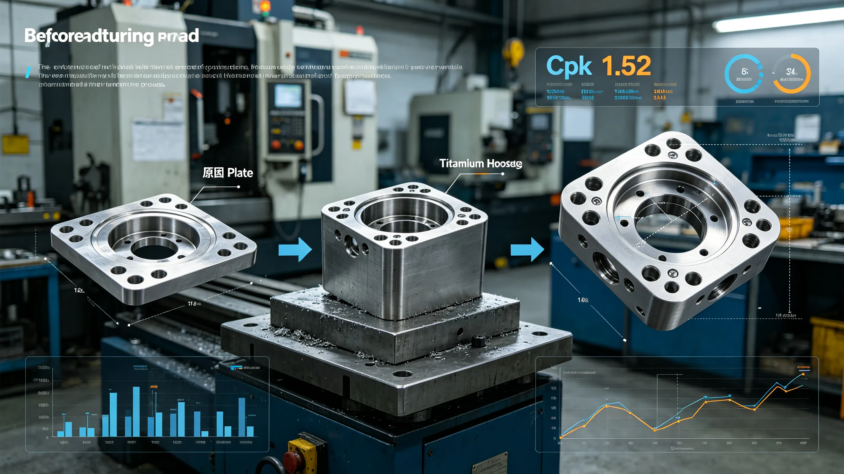
Component overview
The component was a complex titanium housing for an aerospace actuator system, machined from Ti-6Al-4V plate per ASTM B265. The component had multiple precision features — a 100 mm diameter bore with a tolerance of H6, six threaded holes with true position tolerance of 0.05 mm, a sealing surface with a flatness requirement of 0.02 mm, and wall thicknesses ranging from 1.5 mm to 8.0 mm. The overall dimensions were approximately 200 mm by 150 mm by 100 mm. The tolerance requirements for this component align with the precision ranges described in the titanium CNC tolerance guide. The machining sequence leverages 5-axis titanium machining to complete these precision features in fewer setups.
Process development approach
The process development followed a structured approach with three phases. Phase one established the roughing sequence and verified that the material was adequately stress-relieved. Phase two developed the semi-finishing and finishing strategies for each critical feature. Phase three validated the complete process with a production trial of 25 components.
The roughing sequence was designed to remove material symmetrically to manage residual stress redistribution. The component was roughed in three stages — first the external profile, then the internal features from one side, then the internal features from the opposite side. The component was stress-relieved between the roughing stages at 600°C in a vacuum furnace.
Tool selection and validation
The critical bore operation required a tool that could maintain H6 tolerance over a production run. A single-point boring head with a CBN insert was selected. The tool was validated through a tool life study that demonstrated the capability to maintain the required tolerance for 40 components before the insert required indexing.
The threaded holes were produced using thread milling rather than tapping, to provide better tolerance control and longer tool life. The thread milling cutter was a carbide TiSiN-coated tool with a diameter of 6 mm. The thread milling parameters — feed rate, spindle speed, and helical interpolation path — were optimized to achieve the required true position tolerance.
In-process inspection strategy
The in-process inspection strategy included probing after each critical operation. The bore diameter was measured using an air gauge after roughing, semi-finishing, and finishing. The air gauge measurements were correlated with CMM measurements during process validation to verify the correlation.
The flatness of the sealing surface was verified using a laser measurement system after the semi-finishing pass. If the flatness was within 0.04 mm, the finishing pass was performed using the standard parameters. If the flatness exceeded 0.04 mm, a corrective toolpath was generated to bring the surface within tolerance.
Production results
The process capability study based on the 25-component trial showed a Cpk of 1.52 for the bore diameter, 1.38 for the thread true position, and 1.45 for the sealing surface flatness. All values exceeded the minimum Cpk of 1.33 required by the customer.
The production scale-up from the trial to full production was accomplished without significant process changes. The tool life limits established during validation were confirmed in production, and the inspection strategy was reduced from 100 percent inspection to statistical sampling after 100 components were produced with zero non-conformances.
Table 1: Process capability results
| Feature | Specification | Measured range | Cpk | Verification method |
|---|---|---|---|---|
| Bore diameter | H6 (0/+0.022 mm) | +0.008 to +0.016 mm | 1.52 | Air gauge, CMM correlation |
| Thread true position | 0.05 mm | 0.015 to 0.035 mm | 1.38 | CMM |
| Sealing surface flatness | 0.02 mm | 0.008 to 0.016 mm | 1.45 | Laser measurement |
| Wall thickness | 1.5 ±0.10 mm | 1.48 to 1.56 mm | 1.33 | Ultrasonic measurement |
For components with similar tolerance and process requirements, request a process study, and our engineers will outline the machining sequence, tooling, and inspection plan for your geometry.