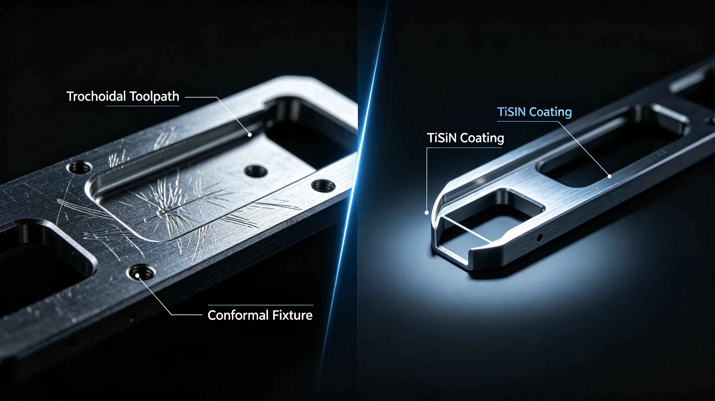
Component overview
The component was an L-bracket for an aerospace structural application, machined from Ti-6Al-4V plate per ASTM B265, Grade 5, annealed. The bracket had a wall thickness of 1.2 mm with a wall height of 18 mm, giving an aspect ratio of 15 to 1. The overall dimensions were approximately 120 mm by 80 mm by 30 mm. The critical tolerances were ±0.05 mm on the mounting surface flatness and ±0.10 mm on the hole positions.
Initial challenges
The initial machining approach used conventional contour-parallel toolpaths with a 10 mm carbide end mill. The first components showed wall deflection of 0.12 to 0.18 mm at the top of the wall, and the flatness of the mounting surface was 0.08 to 0.12 mm — both outside the print tolerance. This deflection behavior is consistent with the thin-wall machining guidelines, which identify aspect ratios above 12 to 1 as requiring specialized fixturing and toolpath strategies.
Vibration marks were visible on the wall surface at the mid-height region, corresponding to the point where the wall stiffness decreased below the threshold for stable cutting. Tool life was limited to two components per tool before the surface finish degraded beyond the acceptable limit.
Process development
The fixturing was changed from a standard vise to a custom fixture with a conformal pocket that supported the wall along its full height. The fixture included a clamping plate that applied uniform pressure across the top of the bracket rather than point clamping at the edges.
The toolpath was changed from contour-parallel to trochoidal with a constant radial engagement of 8 percent of the tool diameter. The finishing passes were reduced from one pass at 0.3 mm stock removal to three passes at 0.15 mm, 0.10 mm, and 0.05 mm.
The tool was changed from a standard-carbide end mill to a tool with a TiSiN coating and a 0.4 mm nose radius. The cutting speed was reduced from 55 m/min to 48 m/min, and the feed rate was adjusted to maintain a chip load of 0.04 mm per tooth.
Results
After process development, the wall deflection was reduced to 0.03 to 0.05 mm, within the print tolerance. The mounting surface flatness was 0.02 to 0.04 mm. Tool life increased to eight components per tool. The surface finish was Ra 0.6 to 0.8 μm, meeting the print requirement of Ra 1.6 μm maximum.
Key lessons
The fixturing change had the largest single effect on component quality. The conformal pocket that supported the thin wall along its full height eliminated the deflection that was the primary source of dimensional non-compliance.
The trochoidal toolpath with constant engagement was essential for maintaining consistent wall thickness. The variable engagement of the conventional toolpath produced corresponding variation in wall deflection and thickness.
The three-pass finishing sequence allowed the wall to stabilize between passes, and the final 0.05 mm pass produced a clean surface with minimal cutting force.
For thin-wall titanium components with similar deflection and tolerance requirements, request a process study and our engineers will recommend the fixturing and toolpath strategy for your geometry.
Table 1: Process parameters before and after development
| Parameter | Initial approach | Optimized approach |
|---|---|---|
| Fixturing | Standard vise | Conformal pocket fixture |
| Toolpath | Contour-parallel | Trochoidal, 8% radial engagement |
| Finishing passes | 1 pass at 0.3 mm | 3 passes at 0.15/0.10/0.05 mm |
| Tool coating | Uncoated carbide | TiSiN coated |
| Cutting speed | 55 m/min | 48 m/min |
| Tool life | 2 components | 8 components |
| Wall deflection | 0.12–0.18 mm | 0.03–0.05 mm |