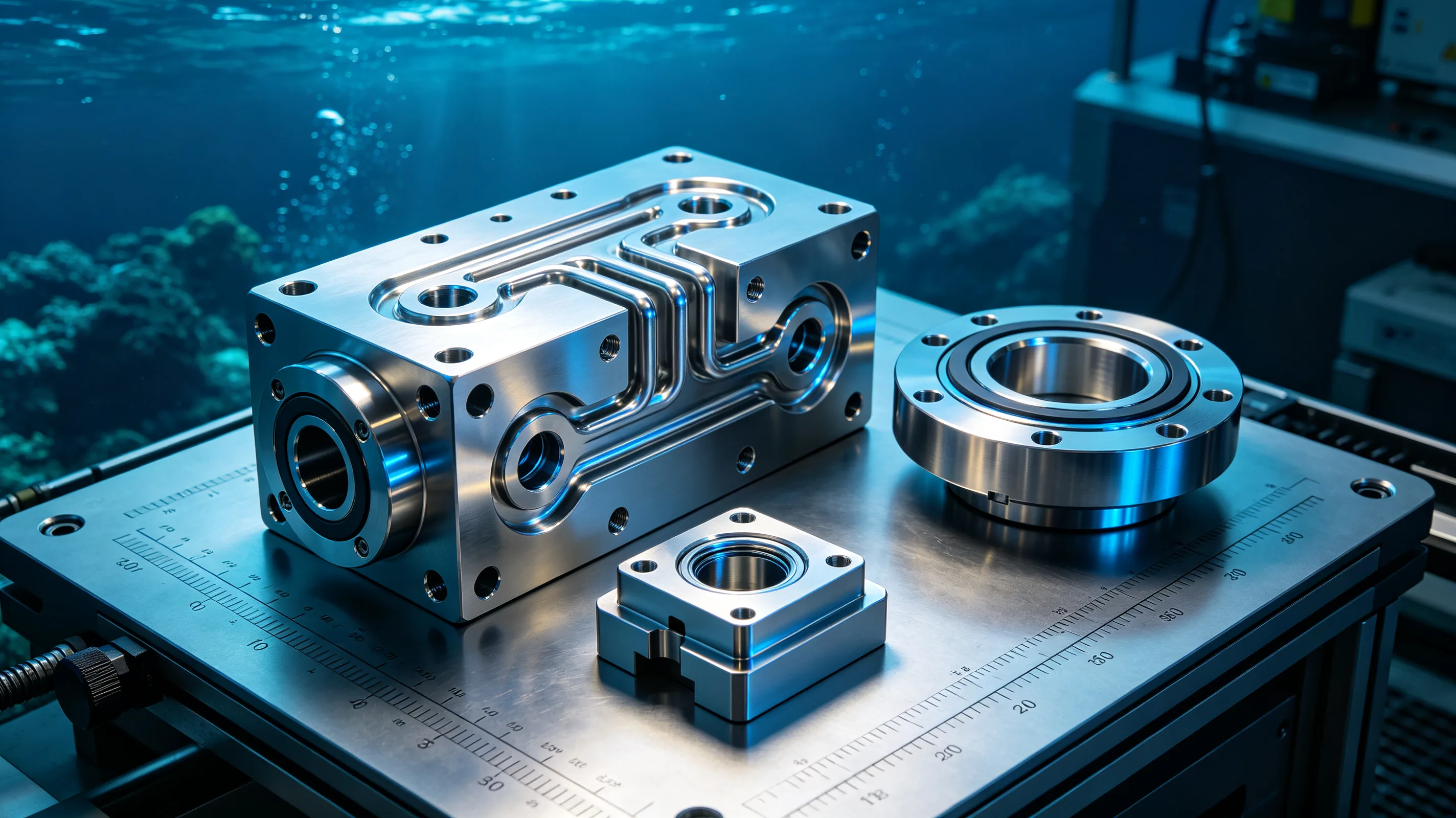
Subsea component machining operates within a precision regime that is distinct from other high-precision manufacturing sectors. While aerospace components prioritise weight minimisation and fatigue life at high cycle counts, and medical implants prioritise biocompatibility and surface finish, subsea components must maintain sealing integrity and structural function through decades of immersion in a corrosive, high-pressure environment where intervention for repair is economically prohibitive. This article examines the precision requirements that govern subsea component machining — the tolerance bands, geometric controls, surface integrity specifications, and metrology methods that differentiate subsea manufacturing from general industrial CNC machining. For engineers and procurement teams specifying subsea components, understanding these precision requirements is essential for selecting capable machining suppliers and avoiding costly non-conformances during equipment integration and commissioning.
Executive summary
Subsea component machining precision requirements are defined by a combination of industry standards (API 6A, API 17D, ISO 13628, NORSOK M-001), classification society rules (DNV, ABS, Lloyds), and equipment-specific specifications from system integrators. The most demanding precision features fall into three categories: sealing surfaces, which require flatness within 0.013 mm and surface finish Ra ≤ 0.4 µm for metal-to-metal seals; threaded connections, which demand pitch diameter control within ±0.025 mm and thread form verification by profile measurement; and pressure-retaining features, which require wall thickness uniformity within ±0.1 mm for burst pressure predictability. Achieving these precisions on subsea components — which are often large (exceeding 500 kg), made of difficult-to-machine materials (Ti-6Al-4V, Alloy 625, superduplex stainless steels), and geometrically complex — requires machine tools with thermal stability control, cutting tools designed for the specific material behaviour, and metrology equipment capable of verifying features at the micrometre level across workpiece dimensions of hundreds of millimetres.
Sealing surface precision requirements
Subsea equipment relies on metal-to-metal seals and elastomer-energised seal assemblies to contain wellhead pressure that can exceed 15,000 psi (103.4 MPa) in high-pressure high-temperature (HPHT) applications. The precision of the sealing surfaces directly determines whether the equipment maintains pressure integrity over its design life.
Flatness and surface finish specifications
Metal-to-metal sealing surfaces — used in subsea tree connectors, wellhead mandrels, flowline termination hubs, and valve gate faces — are specified with flatness tolerances of 0.013 mm total indicator reading (TIR) across the sealing face. This flatness requirement applies regardless of the sealing face diameter, which can range from 50 mm for small-bore connectors to 600 mm for large-bore production tree connectors. Surface finish requirements for metal-to-metal seals are specified at Ra 0.2–0.4 µm, with some HPHT applications requiring Ra ≤ 0.2 µm on the seal face.
Machining these surfaces on large-diameter titanium or alloy 625 components requires attention to machine tool thermal behaviour. The heat generated by the cutting process and the machine tool spindle motor causes thermal expansion of the workpiece and machine structure that, if uncompensated, produces convex or concave sealing faces that violate the flatness specification. Coolant temperature control within ±1 °C of the metrology lab temperature, a stabilisation dwell period of 15–30 minutes before the finish pass, and in-process probing to measure face flatness and adjust the toolpath are standard practices.
Seal groove geometry control
Elastomer-energised seal assemblies — O-rings, T-seals, spring-energised seals — require groove dimensions that control seal compression within a defined range. Groove depth tolerances of ±0.025 mm and groove width tolerances of ±0.05 mm are typical. Groove bottom surface finish is specified at Ra 0.8 µm maximum to prevent leakage past the seal static interface. Groove side wall finish at Ra 1.6 µm is sufficient for most seal types.
Groove machining on subsea components is typically performed by grooving tools or end mills with corner radius control. The transition radius between the groove bottom and side wall must match the seal manufacturer specification — typically R0.1–R0.4 mm depending on seal cross-section. Undercuts or burrs at the groove edge cause seal damage during assembly and are not acceptable. Deburring of groove edges is performed by precision brushing or manual deburring with controlled edge break specification, not by abrasive blasting that could alter groove dimensions.
Surface integrity requirements for sealing faces
The sealing surface of a subsea component must maintain its dimensional precision and sealing function through repeated make-and-break cycles during equipment installation, intervention, and recommissioning. Machining-induced surface damage — feed marks, surface tears, microcracks, and embedded carbide particles — reduces the effective contact area of the seal and creates leakage paths.
Surface integrity requirements for subsea sealing surfaces include the following. Feed mark depth must not exceed 0.2 µm for metal-to-metal seals. There must be no visible surface tears or laps. Carbide particle contamination from tool wear must be prevented through coolant filtration below 10 µm and use of sharp, undamaged inserts. Post-machining surface inspection using replication techniques or optical profilometry is specified for critical sealing surfaces to confirm surface integrity before assembly.
Threaded connection precision requirements
Subsea threaded connections — used in connector bolts, valve bonnet studs, instrument tubing fittings, and casing hanger connections — must maintain preload and sealing function through thermal cycling, vibration, and corrosion exposure over decades of service.
Pitch diameter and thread form control
Pitch diameter tolerance for subsea bolting threads per API 7-2 is ±0.025 mm for thread sizes through M100. Thread form is specified to Unified Inch or ISO metric tolerance classes, with thread flank angle tolerance of ±0.5 degrees and thread height tolerance of ±0.025 mm.
Thread milling is the preferred machining method for titanium subsea threaded components. Thread milling produces consistent thread form by generating the thread through a helical interpolation toolpath rather than a single-point forming action, reducing the risk of thread tearing and surface defects that occur with thread turning on titanium. Thread milling tool selection must match the thread form specification — full-profile thread mills produce the most consistent thread form, while insert-type thread mills offer flexibility for non-standard thread sizes.
Thread inspection methods
Thread inspection for subsea components goes beyond Go/No-Go gauging. The following inspection methods are specified depending on the thread criticality.
Go/No-Go gauging per API 7-2 or ISO 1502 is the first-level inspection for all subsea threaded connections. Gauges must be certified to NIST-traceable standards with calibration intervals not exceeding 12 months.
Three-wire pitch diameter measurement is specified for threads where pitch diameter control is critical. The measurement is performed using calibrated wires of the diameter specified for the thread pitch, with the measurement result corrected for thread form deviation if required by the thread standard.
Thread profile measurement using optical comparators or contact profilometers is specified for HPHT threads and threads subject to fatigue loading. The profile measurement verifies thread flank angle, thread height, root radius, and crest flatness against the thread form specification. Profile measurement frequency is typically one thread per component for production components, with every thread measured for first-article components.
Thread surface finish requirements
Thread surface finish for subsea connections is specified at Ra 0.8–1.6 µm for the thread flanks and root. Rougher surfaces increase friction during make-up, reducing preload consistency and increasing the risk of galling, particularly on titanium threads where the high coefficient of friction and tendency to gall are well documented.
Thread surface finish is controlled through the thread milling feed rate — feed per tooth of 0.02–0.05 mm produces consistent surface finish in the Ra 0.8–1.6 µm range for Ti-6Al-4V. Thread turning, where specified, requires wiper geometry inserts and feed rates below 0.08 mm/rev to achieve comparable surface finish. Post-machining thread cleaning by solvent wash and compressed air drying removes chip debris and cutting fluid residue that could interfere with thread gauge measurement.
Pressure-retaining feature precision requirements
Subsea components that contain internal pressure — valve bodies, connector hubs, manifold blocks, and tubing hangers — are machined to dimensional tolerances that ensure predictable burst pressure and fatigue life.
Wall thickness uniformity
Wall thickness of pressure-retaining features is specified with tolerances of ±0.1 mm for components rated to 10,000 psi working pressure and ±0.05 mm for HPHT components rated to 15,000 psi and above. Wall thickness is verified by ultrasonic gauging at defined measurement points specified on the component drawing.
Machining to these wall thickness tolerances on subsea components presents the challenge of maintaining concentricity between internal bores and external surfaces when the component is machined in multiple setups. Machining strategy must account for the wall thickness specification at the roughing stage — excessive stock removal on one side of the component during roughing limits the ability to correct wall thickness variation during finish machining. Probing cycles that measure bore position and external surface position relative to the machine coordinate system enable the CAM programme to adjust the finish toolpath to achieve specified wall thickness.
Bore diameter and roundness control
Bore diameter tolerances for pressure-retaining features range from ±0.025 mm for small-diameter bores (under 50 mm) to ±0.05 mm for large-diameter bores (over 200 mm). Roundness tolerance is typically specified at 0.01 mm total indicator reading. These tolerances ensure that pressure-containing components conform to the stress analysis assumptions used in the design.
Bore machining for subsea components in titanium requires rigid tool support to prevent chatter that degrades bore roundness and surface finish. Boring bars with diameter-to-length ratios not exceeding 4:1 are standard for subsea component boring operations. Where deep bores require length-to-diameter ratios above 4:1, dampened boring bars or pilot boring sequences are used to maintain bore geometry. In-process bore gauging — using air gauging or electronic bore plugs — provides real-time dimensional feedback that enables tool offset adjustment during the machining cycle.
| Feature Type | Typical Tolerance | Machining Method | Verification Method | Typical Material |
|---|---|---|---|---|
| Metal-to-metal seal face flatness | 0.013 mm TIR | Finish facing with wiper insert | Laser interferometer, straightedge | Ti-6Al-4V, Alloy 625 |
| Seal surface finish | Ra 0.2–0.4 µm | Wiper insert, feed <0.05 mm/rev | Contact profilometer, optical profiler | Ti-6Al-4V, Alloy 625 |
| Thread pitch diameter | ±0.025 mm | Thread milling | Three-wire measurement, thread gauge | Ti-6Al-4V, Grade 23 |
| Bore diameter (under 50 mm) | ±0.025 mm | Boring, reaming | Air gauge, bore plug gauge | Ti-6Al-4V, 25Cr Duplex |
| Bore diameter (over 200 mm) | ±0.05 mm | Boring with steady rest | CMM scanning, internal micrometre | Ti-6Al-4V, Alloy 625 |
| Wall thickness | ±0.1 mm (10 ksi), ±0.05 mm (15 ksi) | Multi-setup machining | Ultrasonic gauging | Ti-6Al-4V, Alloy 625 |
| Bolt hole position | 0.1 mm true position diam. | Drilling with spotting cycle | CMM position measurement | Any subsea grade |
| Groove depth | ±0.025 mm | Grooving tool, end mill | Depth micrometre, CMM | Ti-6Al-4V, Alloy 625 |
Metrology methods for subsea component verification
Verification of subsea component precision requirements relies on metrology methods that provide measurement uncertainty sufficiently below the tolerance band — typically a 10:1 test uncertainty ratio (TUR) or as close to it as practically achievable.
Laser interferometry for flatness
Sealing surface flatness is verified by laser interferometry using a laser plane generator and digital receiver that measures flatness deviations in increments of 0.001 mm. The measurement is performed in the inspection lab at controlled temperature (20 ±1 °C) after the component has stabilised for a minimum of 4 hours. The flatness measurement report includes a contour map of the sealing face with high and low points identified.
Coordinate measuring machine verification
CMM verification is used for the majority of subsea component dimensional features — bore diameters, bore positions, bolt hole patterns, flange face parallelism, and overall component envelope dimensions. CMM inspection programmes are developed from the component CAD model and verified against the drawing tolerance requirements. Measurement results are reported with measurement uncertainty budgets that document the contribution of each measurement stage to the overall uncertainty.
For large subsea components exceeding the capacity of standard CMMs — flange faces above 600 mm diameter, components over 1,000 mm in length — portable CMM arms or laser trackers are used. Laser tracker accuracy of ±0.015 mm over 2 m range is typical for subsea component verification. Measurement uncertainty for portable metrology is evaluated through repeated measurements of reference features and comparison with fixed CMM measurements where possible.
Surface finish measurement
Surface finish of sealing surfaces and thread flanks is measured using contact profilometers with stylus tip radius of 2 µm or 5 µm depending on the surface specification. Measurement parameters include Ra (arithmetic mean roughness), Rz (average maximum height), and Rmax (maximum individual peak-to-valley height). For sealing surfaces, the measurement traverse length must be at least five times the expected roughness wavelength to provide a statistically representative measurement.
Non-contact optical profilometry is increasingly specified for sealing surface measurement on titanium components. Optical methods avoid the risk of stylus damage to soft titanium surfaces and provide areal surface characterisation (Sa, Sz, Sdr) that more completely describes the sealing surface topography than single-line profilometry.