5-Axis Machining for Titanium Parts: When Is It Necessary?
Executive summary: Five-axis machining becomes necessary for titanium parts when geometry cannot be accessed from a single tool orientation, when tight tolerances require fewer setups, or when contoured surfaces need consistent tool orientation. The decision is economic as much as technical. A 5-axis machine reduces fixture handling, improves accuracy between features, and allows optimal tool angles for titanium's thermal and mechanical behavior. However, 5-axis programming and machine time are more expensive than 3-axis. For simple prismatic parts, 5-axis adds cost without benefit. For complex aerospace, medical, and defense components, it is often the only practical way to hold tolerance and complete the geometry.
Geometric indicators that require 5-axis
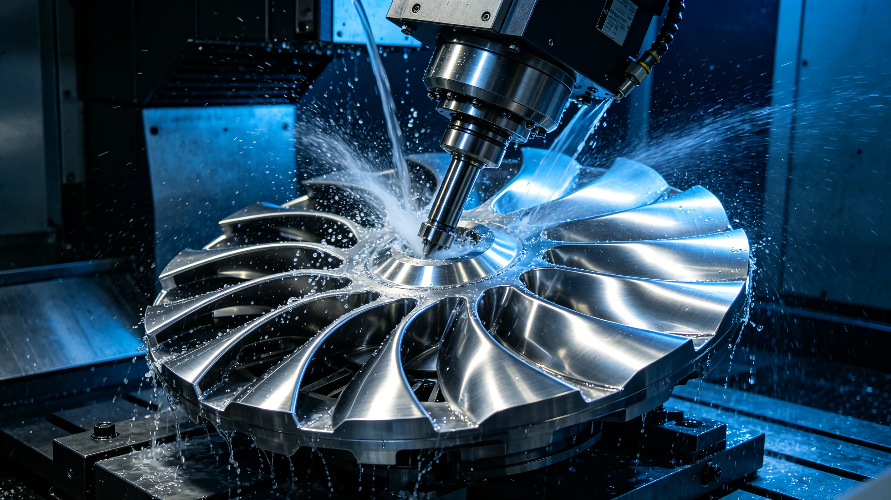
The clearest signal for 5-axis machining is features that cannot be machined from a single tool approach direction. Undercuts, internal cavities with drafted walls, impeller blades, turbine blisks, and orthopedic implants all have surfaces that a 3-axis spindle cannot reach. Even if the feature could be reached with long tools or special angle heads, the resulting tool overhang and poor chip evacuation make the process unreliable in titanium.
Contoured surfaces are another indicator. When a surface has continuously varying curvature, a 3-axis toolpath produces scallops and varying engagement that are difficult to finish consistently. Five-axis machining keeps the tool oriented normal or at a constant angle to the surface, producing uniform cusp height and better surface finish. This matters for aerodynamic surfaces, sealing faces, and implant articulating surfaces.
| Part characteristic | 3-axis adequate | 3+2 preferred | 5-axis necessary |
|---|---|---|---|
| Open pockets on one face | Yes | Optional | No |
| Features on multiple orthogonal faces | No | Yes | No |
| Contoured freeform surfaces | No | Limited | Yes |
| Undercuts or re-entrant features | No | No | Yes |
| Tight positional tolerance across faces | Risky | Yes | Yes |
| Blisks, impellers, turbine blades | No | No | Yes |
| Deep cavities with drafted walls | No | No | Yes |
Setup reduction and tolerance benefits
Every setup change introduces positioning error. Even on a well-maintained machine, refixturing a titanium part can introduce 0.01 to 0.03 mm of positional variation between features. For tolerances of ±0.05 mm or looser, this is acceptable. For tolerances of ±0.025 mm or tighter, multiple setups become a risk.
Five-axis machining can often complete a complex part in one or two setups instead of four or five. This reduces the accumulated error from fixture datums and improves repeatability. It also reduces handling time and the opportunity for damage to thin features or precision surfaces between setups.
For titanium, setup reduction has an additional thermal benefit. Each setup requires warm-up and alignment time. Repeated thermal cycles between setups can shift the part as it reaches equilibrium. Machining more features in a single continuous setup reduces this thermal variation.
Tool orientation advantages for titanium
In 3-axis machining, the tool axis is fixed in Z. The tool cuts with its bottom at the center, where surface speed is zero, and with its side where surface speed is highest. This creates a temperature gradient across the tool and a rubbing condition at the center. In titanium, the rubbing zone is where built-up edge and smearing occur.
Five-axis machining tilts the tool so that cutting occurs along the side of the tool, away from the zero-speed center. This produces cleaner shearing, better chip formation, and lower peak temperature. It also directs a portion of the cutting force axially into the spindle, the stiffest direction of the machine, reducing tool and workpiece deflection.
For thin-wall titanium parts, this force redirection is particularly valuable. The reduced radial component lowers wall deflection and improves dimensional accuracy. For deep pockets, tilting the tool improves chip evacuation by allowing coolant and chips to flow away from the cutting zone instead of packing into the bottom of the pocket.
Cost considerations and break-even analysis
Five-axis machining is not automatically more expensive per part. The machine hourly rate is higher, but the total process may be cheaper when setup reduction is significant. A part that requires five 3-axis setups might be completed in two 5-axis setups. The savings in fixture design, inspection, and handling can offset the higher machine rate.
The break-even depends on geometry complexity and batch size. For prototypes or very small batches, 3+2 positioning on a 5-axis machine is often sufficient and faster to program than full simultaneous 5-axis. For production batches of complex parts, simultaneous 5-axis can reduce cycle time and improve consistency enough to justify the investment.
| Cost element | 3-axis | 5-axis |
|---|---|---|
| Machine hourly rate | Lower | Higher |
| Number of setups | More | Fewer |
| Fixture complexity | More fixtures | Often one complex fixture |
| Programming time | Lower | Higher |
| Inspection between setups | More frequent | Less frequent |
| Scrap risk from setup error | Higher | Lower |
| Best suited for | Simple prismatic parts | Complex contoured parts |
When 3+2 is enough
Not all 5-axis work requires simultaneous motion. Three-plus-two machining positions the tool at a fixed angle using the rotary axes, then machines with three linear axes. The rotary axes do not move during the cut. This approach is simpler to program, more rigid, and often faster for features that can be machined from a few discrete orientations.
Three-plus-two is ideal for parts with features on multiple faces but no continuous contoured surfaces. A box-shaped manifold with ports on several faces, for example, can often be completed with 3+2 positioning. The benefits are setup reduction and improved access without the programming complexity of simultaneous 5-axis.
Simultaneous 5-axis becomes necessary when the tool must continuously change orientation to follow a contoured surface or avoid collisions. The programming is more demanding, and the machine motion must be smooth to avoid visible toolpath marks. For titanium, simultaneous finishing also helps distribute heat across the tool surface because the engagement point changes continuously.
Evaluating supplier 5-axis capability
Not every shop with a 5-axis machine can machine titanium effectively. The combination of 5-axis motion and titanium cutting conditions requires machine rigidity, adequate spindle torque, high-pressure coolant, and proven CAM strategies. A machine designed for aluminum mold work may not have the spindle torque or rigidity for titanium aerospace components.
Key questions to ask a supplier include: What is the maximum workpiece size and weight on the 5-axis table? Is high-pressure through-spindle coolant available? What CAM system and simulation software are used for 5-axis toolpaths? What experience exists with similar titanium alloys and geometries? Can they provide first-article inspection data and tool life records?
For programming best practices once 5-axis is selected, see the 5-axis titanium machining best practices guide. For an overview of titanium CNC capabilities, visit the titanium CNC machining services page.
Decision rules for procurement teams
Rule 1 — Require 5-axis only when geometry or tolerance demands it. Do not specify 5-axis for simple prismatic parts. Use 3-axis or 3+2 when they can meet the drawing.
Rule 2 — Compare total process cost, not machine rate. A higher hourly 5-axis rate may produce a lower total cost by reducing setups, fixtures, and scrap.
Rule 3 — Verify titanium-specific 5-axis experience. Ask for similar parts, alloy grades, and inspection results before awarding complex titanium 5-axis work.
To discuss whether your titanium component needs 5-axis machining, request a quote with your geometry and tolerance requirements.