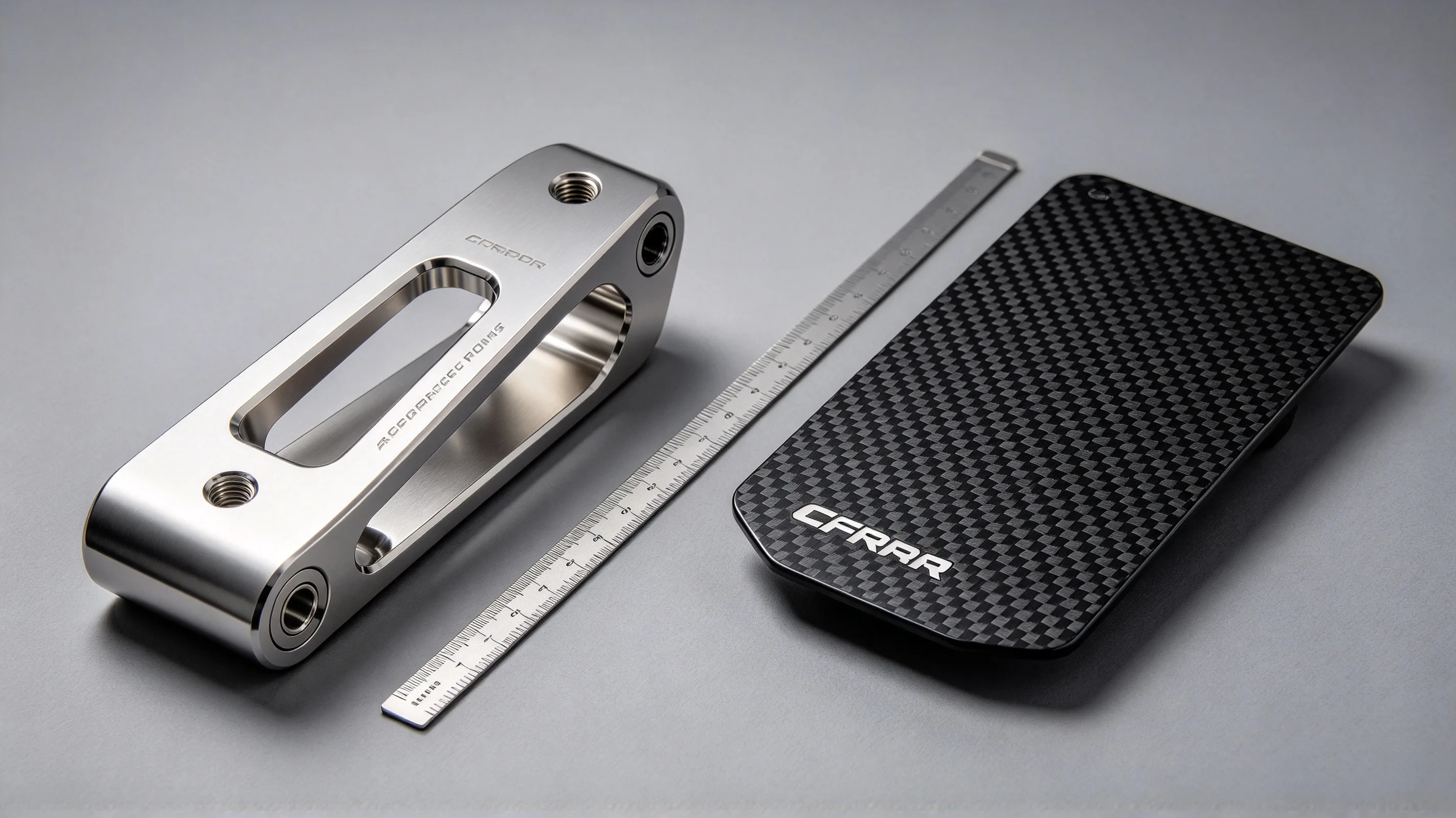
Titanium and carbon fiber reinforced polymer (CFRP) are the two materials that have driven the weight reduction in aerospace, motorsport, and high-performance industrial applications over the last 40 years. Each material dominates in different load cases, and the choice between them is one of the most consequential engineering decisions in a high-performance design. The wrong choice is paid in either weight that could have been saved, or in cost and manufacturing complexity that could have been avoided. The right choice is driven by the specific load case, the specific manufacturing capability, and the specific operating environment — and the decision framework below is the engineering discipline for getting the choice right.
This article works through the four decision dimensions that drive the titanium vs CFRP choice: specific strength and specific stiffness, fatigue and damage tolerance, environmental resistance (corrosion, temperature, galvanic compatibility), and manufacturing cost and complexity. It assumes the general material selection guide, the Grade 5 material guide, and the machining processes guide as background — those cover the broader material and process landscape; here we focus on the comparison with CFRP specifically. For the design side, the DFM guide is the cross-reference.
- Why titanium and CFRP are the two competing premium materials
- Specific strength and specific stiffness
- Fatigue and damage tolerance
- Environmental resistance: corrosion, temperature, galvanic compatibility
- Manufacturing cost and complexity
- Joining titanium to CFRP and to other metals
- Decision framework: when to choose which
- Titanium vs CFRP selection checklist
Why titanium and CFRP are the two competing premium materials
Titanium and CFRP are both premium materials — high cost per kg, high value per unit weight, and high performance in the load cases they are designed for. The cost is roughly comparable on a per-part basis for high-performance applications (a CFRP autoclave-cured part and a Ti-6Al-4V machined part can both be in the 5,000 range), but the cost per kg is different (titanium at 100/kg vs CFRP prepreg at 200/kg), and the cost per kg of finished weight is different (titanium is denser and uses more material per part). The choice is not about which material is cheaper; the choice is about which material delivers the right performance for the load case at the right manufacturing cost.
The industries where the titanium vs CFRP choice is consequential are:
- Aerospace primary and secondary structure. Wing skins, fuselage frames, control surfaces, landing gear, helicopter rotor blades.
- Motorsport chassis and bodywork. Formula 1, WEC, NASCAR chassis; body panels; suspension components.
- High-performance industrial. Pressure vessels, robotic arms, high-speed machinery, medical imaging equipment.
In each of these industries, the question is the same: for the specific load case, is the better material titanium (with its combination of high specific strength, high temperature capability, and isotropic properties) or CFRP (with its combination of very high specific stiffness, lower density, and anisotropic properties that can be tailored to the load case)? The answer depends on the four decision dimensions below.
Specific strength and specific stiffness
Specific strength (strength per unit density) and specific stiffness (modulus per unit density) are the most-cited metrics for material selection in weight-critical applications, and they are the right starting point for the titanium vs CFRP comparison. The numbers below are for the typical aerospace grades of each material:
| Material | Density (g/cm³) | Tensile Strength (MPa) | Specific Strength (kN·m/kg) | Elastic Modulus (GPa) | Specific Modulus (MN·m/kg) |
|---|---|---|---|---|---|
| Ti-6Al-4V (Grade 5) | 4.43 | 895–1,100 | 200–250 | 110–115 | 25–26 |
| Ti-10V-2Fe-3Al (beta) | 4.65 | 1,100–1,250 | 235–270 | 100–110 | 22–24 |
| CP Grade 2 | 4.51 | 345–460 | 75–100 | 100–105 | 22–23 |
| CFRP (HS carbon, 60% fibre, quasi-iso) | 1.55 | 600–900 | 385–580 | 55–70 | 35–45 |
| CFRP (IM carbon, 60% fibre, unidirectional) | 1.55 | 1,200–1,800 | 775–1,160 | 130–160 | 85–105 |
| Aluminium 7075-T6 | 2.81 | 570–620 | 200–220 | 70–72 | 25–26 |
| Steel 4340 | 7.85 | 1,100–1,250 | 140–160 | 190–210 | 24–27 |
The table tells the engineering story:
-
CFRP unidirectional has 3–4× the specific strength of titanium. The 775–1,160 kN·m/kg range for unidirectional CFRP is roughly 3× the 200–250 kN·m/kg range for Grade 5, and the advantage is even larger against the heavier beta alloys. For applications where specific strength is the binding metric (rocket motor casings, pressure vessels, high-stress tension members), CFRP is the clear winner.
-
CFRP unidirectional has 3–4× the specific stiffness of titanium. The 85–105 MN·m/kg range for unidirectional CFRP is roughly 4× the 25–26 MN·m/kg range for Grade 5. For applications where stiffness is the binding metric (wing skins, control surfaces, robotic arms, any structure where deflection is the design driver), CFRP is the clear winner.
-
Quasi-isotropic CFRP has roughly 2× the specific strength and 1.5× the specific stiffness of Grade 5. The advantage is real but smaller, and quasi-isotropic CFRP is the more typical layup for general structural parts.
-
Beta titanium (Ti-10-2-3) is the only titanium grade that approaches CFRP on specific strength. The 235–270 kN·m/kg range for Ti-10-2-3 STA is roughly half the unidirectional CFRP range, and roughly comparable to quasi-isotropic CFRP.
The caveat is that CFRP is anisotropic. A unidirectional CFRP ply has the 775–1,160 kN·m/kg strength in the fibre direction but only 30–50 kN·m/kg perpendicular to the fibre. A quasi-isotropic layup averages the strength in multiple directions, but the average is the quasi-iso number (385–580), not the unidirectional number. The anisotropy is the engineering challenge of CFRP: the layup must be designed to match the load case, and the design freedom is also the design responsibility. Titanium is isotropic, which simplifies the design and the analysis but caps the specific strength and specific stiffness at the numbers above.
Fatigue and damage tolerance
Fatigue and damage tolerance is the second decision dimension, and the one where the difference between titanium and CFRP is largest.
Titanium fatigue. Titanium has good fatigue resistance, with an endurance limit of roughly 50–60% of the ultimate tensile strength (for Grade 5 in the annealed condition). The fatigue life is predictable and is typically not the binding design constraint for titanium aerospace parts. The fatigue crack growth rate in titanium is well-characterised (per the NASGRO equation or similar), and the damage tolerance analysis is standard. The fatigue limit is reduced by surface condition (a rough surface reduces the limit by 10–20% relative to a polished surface), by residual stress (a tensile residual stress reduces the limit), and by mean stress (a tensile mean stress reduces the limit by 10–30% relative to a fully reversed loading).
CFRP fatigue. CFRP has excellent fatigue resistance in the fibre direction, with a fatigue limit of roughly 70–80% of the ultimate strength (compared to 50–60% for metals). The damage mode in CFRP fatigue is not crack growth; it is progressive matrix cracking, fibre-matrix debonding, and delamination. The damage accumulates over the fatigue life, and the stiffness and strength degrade progressively rather than catastrophically. The damage is detectable by ultrasonic inspection or by modal analysis, but the detection threshold is typically 1–5% stiffness loss, which is well before the part fails. The “no crack growth” behaviour of CFRP is the source of the “fail-safe” reputation of CFRP structures in aerospace.
The damage tolerance behaviour is the most important practical difference between the two materials. A titanium part with a fatigue crack that exceeds the critical crack length will fail catastrophically, often without warning. A CFRP part with fatigue damage will lose stiffness gradually, and the damage can be detected by inspection before the part reaches the critical damage state. The fail-safe behaviour of CFRP is the reason CFRP is preferred for primary structure in modern commercial aircraft (Boeing 787, Airbus A350), where the design requirement is that the structure must be able to sustain visible damage and remain operational for a specified time (the “damage tolerance” requirement in 14 CFR 25.571).
The trade-off is that CFRP damage is not visually inspectable to the same degree as a metal crack. A metal crack is visible on a surface as a sharp line; a CFRP delamination is internal and requires ultrasonic or X-ray inspection. The inspection cost for CFRP is typically 3–5× the inspection cost for a metal part, and the inspection infrastructure (ultrasonic scanners, X-ray systems, trained NDT inspectors) is a significant capital investment.
Environmental resistance: corrosion, temperature, galvanic compatibility
Environmental resistance is the third decision dimension, and the one where titanium is the clear winner in most cases.
Corrosion. Titanium is essentially immune to corrosion in the environments that matter for aerospace and motorsport (atmospheric exposure, salt spray, fuel, hydraulic fluid, mild acids). The passive TiO₂ film is self-healing and provides long-term protection without surface treatment. CFRP is a polymer matrix with carbon fibre reinforcement, and the polymer matrix is susceptible to UV degradation, moisture absorption, and chemical attack from fuels and hydraulic fluids. The matrix is typically protected by a surface coating or paint, and the protection must be maintained over the part’s service life. A coating failure exposes the matrix to the environment, and the matrix degradation is typically faster than the titanium equivalent.
Temperature. Titanium retains its strength and stiffness up to roughly 300–400 °C (depending on the grade), and the strength reduction above 200 °C is gradual. CFRP is limited by the matrix — the standard epoxy matrix loses significant strength above 120–150 °C, and the high-temperature bismaleimide or polyimide matrices are limited to 200–250 °C. For applications above 200 °C (engine nacelles, exhaust-adjacent structure, supersonic aerodynamics), titanium is the only choice.
Galvanic compatibility. This is the most under-appreciated environmental issue. When titanium and aluminium are in contact in a wet environment, the aluminium corrodes (the aluminium is the anode in the galvanic couple). When CFRP and aluminium are in contact in a wet environment, the aluminium corrodes (the carbon fibre is the cathode in the galvanic couple, and the aluminium is the anode). When titanium and CFRP are in contact in a wet environment, neither corrodes (titanium is the more noble metal, and the carbon fibre is the more noble carbon — the galvanic potential is similar, and the corrosion rate is negligible). The titanium-CFRP combination is galvanically compatible, and the combination does not require the isolation layers that the titanium-aluminium or CFRP-aluminium combinations require.
The galvanic compatibility is the reason titanium-CFRP combinations are common in modern aerospace primary structure. The combination of the lightweight CFRP skin and the titanium fitting gives the best of both materials, and the galvanic compatibility means the combination is durable in the operating environment.
Manufacturing cost and complexity
Manufacturing cost and complexity is the fourth decision dimension, and the one that often determines the choice for production applications. The two materials have fundamentally different manufacturing processes, and the cost structure is correspondingly different.
Titanium manufacturing. Titanium is a metal, and the manufacturing process is the standard metal manufacturing process: mill stock, machined to shape, optionally heat-treated, optionally surface-treated, inspected, and shipped. The manufacturing cost is dominated by the machining time (60–70% of the cost) and the material cost (15–25%). The cycle time is typically 1–4 weeks for a typical aerospace or motorsport part, with the bottleneck being the machining time and the heat treatment queue. The tooling cost is low (a few hundred to a few thousand dollars for a typical fixture and cutting tools), and the minimum order quantity is typically 1–5 parts.
CFRP manufacturing. CFRP is a composite, and the manufacturing process is the standard composite manufacturing process: layup (manual or automated), cure (autoclave, oven, or press), trim, drill, inspect, and ship. The manufacturing cost is dominated by the layup time and the cure time (50–70% of the cost) and the material cost (20–35%). The cycle time is typically 1–6 weeks for a typical autoclave-cured part, with the bottleneck being the layup time and the autoclave queue. The tooling cost is high (a few thousand to tens of thousands of dollars for an autoclave tool), and the minimum order quantity is typically 5–20 parts (because the tooling cost is amortised over the lot).
The cost crossover point is the key metric. For a part with a tooling cost of 5,000. For the same part amortised over 100 parts, the per-part tooling cost is $50. The CFRP process is the right choice when the lot size is large enough to amortise the tooling cost, and the part is light enough to benefit from the CFRP weight saving. The titanium process is the right choice when the lot size is small, the part is complex, or the operating environment is outside the CFRP envelope.
The other manufacturing consideration is the design cycle. A titanium part can be machined from a block of stock, with the design iteration taking days (change the CAM program, cut a new part). A CFRP part requires a new tool for each design iteration, with the iteration taking weeks (change the tool, lay up, cure, ship). The titanium process is the right choice for prototype and low-volume production; the CFRP process is the right choice for high-volume production of a stable design.
Joining titanium to CFRP and to other metals
Joining methods are the practical engineering question that determines whether the titanium-CFRP combination is feasible. The methods are:
Bolted joints. The standard method for titanium-CFRP joints. The titanium fitting has a bolt pattern, the CFRP skin has a matching hole pattern (typically reamed or drilled after cure), and the joint is assembled with titanium bolts, washers, and nuts. The bolt pattern must account for the differential thermal expansion (CFRP is near-zero in the fibre direction, titanium is about 9 ppm/°C), and the bolt pattern must be designed to avoid bearing failure in the CFRP under bearing stress. The titanium bolt is the standard (per AS7469 or AS7479), and the washer must be large enough to distribute the bearing stress below the CFRP bearing allowable (typically 200–400 MPa for unidirectional CFRP, lower for quasi-isotropic).
Bonded joints. The standard method for primary structure. The CFRP skin is bonded to the titanium fitting with a structural adhesive film (e.g., FM300, AF163), and the assembly is co-cured or secondary-bonded in an autoclave. The bonded joint has a higher specific strength than the bolted joint (no hole-drilling in the CFRP), but the joint requires surface preparation (solvent wipe, grit blast, primer) and process control (cure temperature, pressure, vacuum) that the bolted joint does not. The bonded joint is the standard for primary structure on the Boeing 787 and Airbus A350.
Hybrid joints (bolted + bonded). The standard for safety-critical structure. The joint is both bonded (for the primary load path) and bolted (for the redundant load path and the damage-tolerance verification). The hybrid joint combines the specific strength of the bonded joint with the fail-safe behaviour of the bolted joint, and it is the standard for primary structure on modern commercial aircraft.
Mechanical interlock (z-pinning, TuFF). The newest method, with through-thickness reinforcement (z-pins or TuFF — short fibres oriented through the thickness) that provides a mechanical interlock between the CFRP plies. The method is still in development for primary structure, but it is gaining adoption for secondary structure and for repair applications.
The choice between the four methods is driven by the load case, the inspection requirement, and the operating environment. The bolted joint is the simplest and the most inspectable; the bonded joint is the highest-performance; the hybrid joint is the most robust; the mechanical interlock is the most promising. The procurement spec should specify the joint method and the inspection scope at the RFQ stage, and the supplier should have the equipment and the qualified personnel for the specified method.
Decision framework: when to choose which
The decision framework is a decision tree that walks through the four decision dimensions and arrives at the recommended material. The tree is a starting point; the final decision requires engineering judgment for the specific part.
Step 1 — Is the operating temperature above 200 °C? Yes → titanium (CFRP is limited). No → continue.
Step 2 — Is the operating environment galvanically sensitive (aluminium in contact)? Yes → consider CFRP with a titanium fitting, or titanium alone. No → continue.
Step 3 — Is the binding design metric stiffness (deflection-driven)? Yes → CFRP (3–4× specific stiffness of titanium). No → continue.
Step 4 — Is the binding design metric specific strength (load-driven)? Yes → CFRP for high specific strength requirements (2–3× titanium); titanium for moderate specific strength requirements. No → continue.
Step 5 — Is the lot size small (1–10 parts)? Yes → titanium (faster iteration, lower tooling cost). No → continue.
Step 6 — Is the part a complex 3D shape (5-axis, deep cavities, thin walls)? Yes → titanium (CNC machining handles complex shapes; CFRP layup handles complex shapes but with longer lead time). No → CFRP is the recommended choice for stiffness-driven, high-volume, simple-to-moderate-geometry parts.
The decision tree is a starting point, and the final decision requires engineering judgment. The procurement spec should include the material choice and the rationale, and the supplier should be able to support either material or a hybrid combination.
Titanium vs CFRP selection checklist
- Specify the operating temperature, and verify that CFRP is within its temperature envelope (200 °C for standard epoxy, 250 °C for high-temperature matrix). Above 200 °C, titanium is the only choice.
- Specify the operating environment, and verify the galvanic compatibility. CFRP-aluminium and titanium-aluminium joints require isolation layers; titanium-CFRP joints do not.
- Specify the binding design metric (strength, stiffness, fatigue, or a combination), and verify that the material choice matches the metric. CFRP dominates on stiffness; titanium is more isotropic and handles complex 3D shapes.
- Specify the lot size and the design iteration cycle. Titanium is the right choice for small lots and fast iteration; CFRP is the right choice for high-volume production of a stable design.
- Specify the joining method (bolted, bonded, hybrid, or mechanical interlock) and the inspection scope at the RFQ stage.
- Specify the surface treatment for the chosen material. Titanium typically requires pickling + passivation; CFRP typically requires a paint or coating system.
- For hybrid titanium-CFRP parts, specify the surface preparation for the bonded joint, the cure cycle for the adhesive, and the inspection method for the bondline (typically ultrasonic C-scan).
- For prototype runs, prioritise titanium for fast iteration. For high-volume production of a stable design, prioritise CFRP for weight savings.
For a titanium vs CFRP selection review against a specific component, send the print, the load case, the operating environment, and the lot size to the RFQ intake; the engineering team returns a manufacturability feedback with material, joining, and manufacturing recommendations. The 5-axis titanium machining services and engineering review capability at Boze review every titanium-CFRP RFQ against the checklist above before any tooling is ordered, and the typical outcome is a review that surfaces 1–2 material-choice questions per program. For Ti-6Al-4V Grade 5 components in particular, the material choice and the joining method are what determine whether the part meets the weight and the operating-environment targets — and that determination is what drives the buyer’s total cost of ownership over the program.