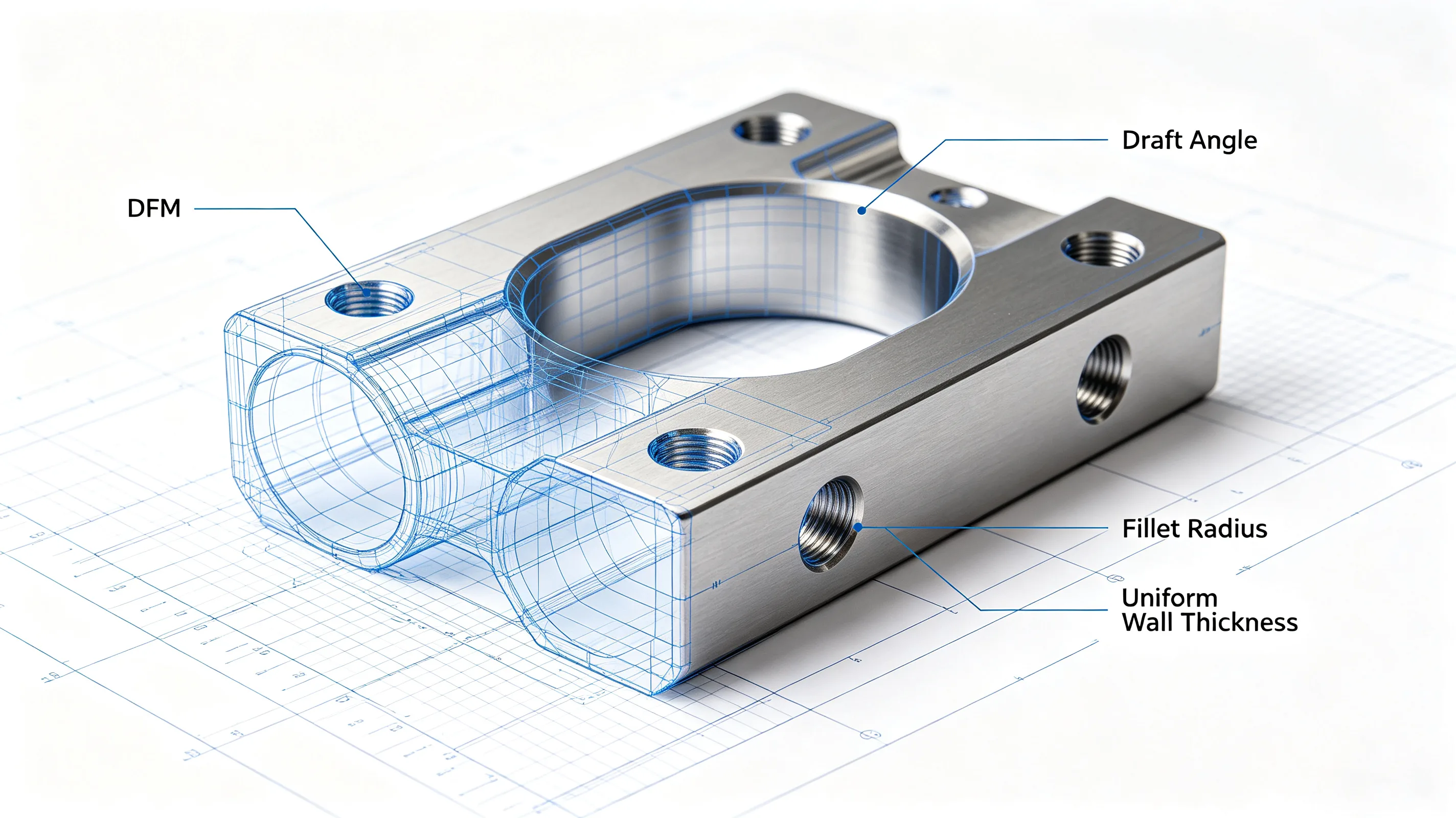
Design for manufacturability for titanium components involves rules that differ from DFM guidelines for steel or aluminum. Titanium’s machining characteristics — high cutting forces, thermal concentration, work hardening, and elastic springback — create constraints on feature geometry that must be considered during the design phase to avoid components that are unnecessarily expensive or difficult to produce. These constraints are detailed in the titanium CNC design guide, which covers wall thickness limits, corner radii, and pocket depth rules, and our engineering support team applies these rules when reviewing customer designs.
Feature geometry rules
Internal corners should be designed with radii that match available tool diameters. A sharp internal corner — one with a radius smaller than the tool radius — requires a smaller tool, which is less rigid and more prone to deflection. The general rule is that the internal corner radius should be at least 1.5 times the tool diameter for standard features and 2.0 times the tool diameter for deep features where tool extension exceeds 4 to 1.
Pocket depth should be limited to 4 times the pocket width for standard machining. Deeper pockets require extended tools, reduced material removal rates, and specialized chip evacuation strategies. If the design requires deeper pockets, they should be specified with a width that allows the use of the largest possible tool.
Wall thickness should be uniform wherever possible. Transitions from thick to thin sections create thermal gradients during machining that lead to differential expansion and potential distortion. If a thickness change is unavoidable, a taper of 1 to 3 degrees is preferred over a step change.
Hole and thread design
Holes should be specified as through-holes rather than blind holes when the design permits. Through-holes provide an exit path for coolant and chips, improving tool life and reducing the risk of chip packing. Blind holes deeper than 3 times the diameter require specialized tooling and should be avoided for high-volume production.
Threads in titanium should be designed with sufficient length to distribute the load. The minimum thread engagement for titanium is 1.5 to 2.0 times the bolt diameter, compared to 1.0 to 1.5 times for steel. Thread rolling is preferred over thread cutting because the cold working process produces a stronger thread with better fatigue resistance.
Thread reliefs should be specified at the base of threaded features to allow the thread cutting tool to run out completely. Without a thread relief, the thread will be incomplete at the bottom, and the effective thread engagement will be less than the specified thread length.
Tolerance rationalization
Specifying tolerances tighter than necessary is the most common DFM error in titanium component design. Every tolerance tighter than ±0.10 mm adds machining time and cost. For titanium, the cost increases disproportionately as tolerances tighten because the material’s machining characteristics make it more difficult to hold tight tolerances than steel or aluminum.
A practical approach is to specify standard tolerances of ±0.10 mm for the majority of features, precision tolerances of ±0.05 mm for features that require it, and high-precision tolerances of ±0.025 mm only for features where the functional requirement genuinely demands it. Use the CNC tolerance checker to validate that your specified tolerances are achievable in titanium.
Material and stock optimization
The material product form should be selected to minimize machining. Components that are primarily round should be designed to be machined from bar stock, which requires less material removal than machining from plate. Components that are flat and thin should be designed to be machined from plate, which requires less machining than bar.
The stock size should be specified to allow for machining allowance on all surfaces. A typical machining allowance for titanium is 1.0 to 2.0 mm per surface for roughing, with an additional 0.3 to 0.5 mm for finishing. Components designed with minimal stock allowance reduce material cost and machining time.
Table 1: DFM rules for titanium CNC components
| Design feature | Recommended practice | Reason |
|---|---|---|
| Internal corner radius | 1.5–0.0x tool diameter | Allows larger, more rigid tools |
| Pocket depth | — x pocket width | Avoids extended tool issues |
| Wall thickness transitions | Tapered, 1–° | Reduces thermal distortion |
| Hole type | Through-hole preferred | Improves chip evacuation |
| Thread engagement | 1.5–0.0x bolt diameter | Ensures adequate thread strength |
| Tolerance | ±0.10 mm standard; tighten only where needed | Reduces machining time and cost |
| Stock form | Match to component geometry | Minimizes material removal |
For a DFM review of your titanium component, submit your design and our engineers will return manufacturability feedback with your quotation.