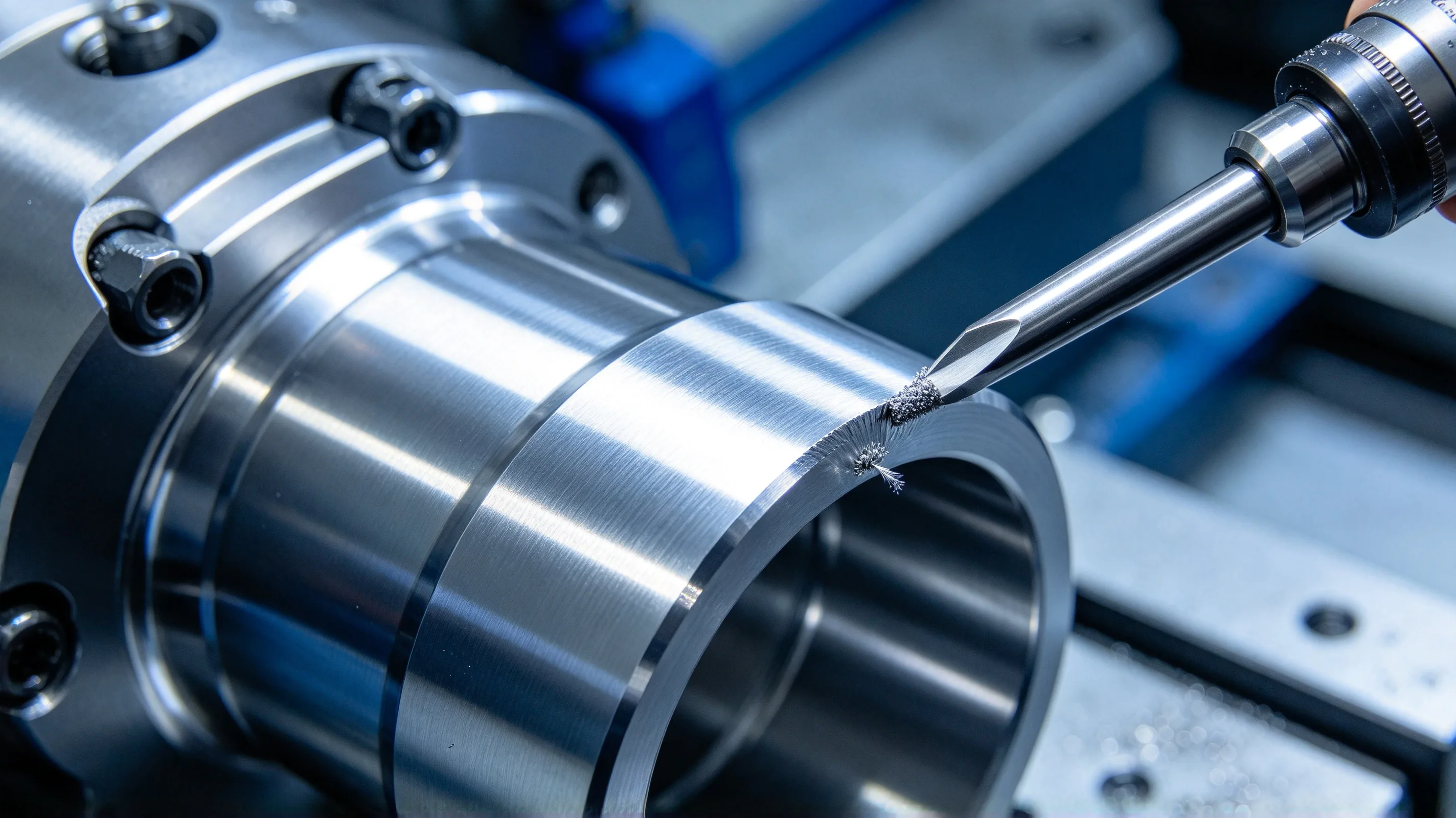
Burrs are the most common surface defect on titanium CNC parts, and the most expensive defect to ignore. A single unaddressed burr on a titanium aerospace bracket can fail an FAI on a controlled edge-break feature, a single unaddressed burr on a titanium PEM electrolyzer bipolar plate can puncture the membrane and fail the stack, and a single unaddressed burr on a titanium medical implant can injure tissue or interfere with the assembly. The cost of deburring a part in-process is typically 1–5% of the part’s machining cost; the cost of skipping the deburring step and finding the burr at final inspection is typically 10–30%, and the cost of finding the burr at the customer’s site is the lost contract on the next order. The procurement question is not “does the part need deburring?” — every titanium CNC part needs some level of deburring. The question is “which deburring method, at which edge-break spec, with which inspection threshold?”
This article works through the four procurement decisions that determine whether a titanium part’s burr spec is correctly specified: burr root causes, burr classification by location and severity, prevention through cutting parameters and tool selection, and deburring method selection. It assumes the titanium machining processes guide and the hole design article as background — those cover the cutting operations; here we focus on the burr that the cutting leaves behind and the methods for removing it. For the tolerance and inspection side, the tolerance cost article and the surface roughness measurement article are the cross-references.
- Why burrs are a disproportionate issue on titanium
- Burr classification by location and severity
- Root causes of burr formation on titanium
- Prevention: cutting parameters and tool selection
- Deburring methods for titanium parts
- Edge-break specification and inspection
- Burr and deburring checklist
Why burrs are a disproportionate issue on titanium
Three material properties make titanium more prone to burr formation than steel or aluminum, and the combination is the reason deburring is a larger line item on titanium parts than on equivalent parts in other materials:
1. Low modulus makes the workpiece spring back at the cut. Titanium’s modulus of about 110 GPa (versus 200 GPa for steel and 70 GPa for aluminum) means the workpiece deflects elastically under the cutting force, and the uncut material on the exit side of the cut is held in place by the elastic deflection rather than being sheared cleanly. When the cut is complete and the cutting force is removed, the elastic deflection recovers, and the uncut material — which is now a thin, partially-attached sliver — springs up as a burr. The lower the modulus, the more elastic deflection, the larger the burr.
2. Low thermal conductivity concentrates heat at the cut. Titanium’s thermal conductivity of about 7 W/m·K (versus 24 for stainless, 167 for aluminum) means the heat from the cut does not dissipate through the workpiece. The localised heating at the cut edge softens the titanium, and the softened material is more prone to plastic deformation and tearing — which produces a thicker, more ragged burr.
3. Work hardening extends the burr beyond the visible edge. Titanium work-hardens rapidly at the cut edge, with a hardened layer that can extend 0.05–0.20 mm beyond the visible cut. The work-hardened layer is more brittle than the base material, and the burr that is left at the cut is partially work-hardened. The work-hardened burr is harder to remove by hand-deburring, by tumbling, or by thermal deburring, and the methods that work on the unhardened base material do not work on the work-hardened burr.
The combined effect is that a titanium part typically requires a more aggressive deburring process than a steel or aluminum part of the same geometry, and the cost of deburring is typically 2–3× the cost of deburring a steel part.
Burr classification by location and severity
The burr on a titanium CNC part falls into one of six location categories, each with its own root cause, its own deburring method, and its own inspection threshold. The classification below is the standard used in the ASME B11.13 burr specification and the ISO 13715 edge-deburring standard.
Class 1 — Rollover burr. The most common burr on a milled or turned edge. A thin sliver of material that is rolled over by the cutting tool but remains attached to the parent material at one end. Typical size: 0.02–0.10 mm thick, 0.1–0.5 mm long. Typical location: the exit side of a milled slot, the end of a turned diameter, the edge of a drilled or bored hole. Removal: tumbling (for cosmetic applications), hand-deburring (for functional edges), thermal deburring (for internal edges).
Class 2 — Cut-off burr. A burr left at the cut-off point when a part is separated from the stock. Typical size: 0.1–0.5 mm thick, 1–5 mm long. Typical location: the center bore of a turned part, the end of a milled profile. Removal: hand-deburring (for external edges), belt sanding (for heavy burrs), thermal deburring (for internal bores).
Class 3 — Poisson burr. A burr raised by the elastic recovery of the workpiece after the cut, caused by low modulus and high cutting force. Typical size: 0.02–0.05 mm thick, 0.1–0.3 mm tall. Typical location: the exit side of a milled pocket on a thin wall, the edge of a precision-bored hole. Removal: thermal deburring (most effective), abrasive flow (for internal features), light hand-deburring.
Class 4 — Tear burr. A burr formed by tearing of the workpiece material at the cut, typically when the cut is interrupted. Typical size: 0.1–0.3 mm thick, 0.5–3 mm long, irregular shape. Removal: hand-deburring (slow), belt sanding, abrasive flow.
Class 5 — Built-up edge (BUE) burr. A burr formed by workpiece material welding to the cutting tool and then transferring back to the part. Typical of low-Vc cutting on titanium, where the BUE breaks off the insert and deposits on the exit side of the cut. Typical size: 0.05–0.20 mm thick, irregular, often discontinuous. Removal: prevention (raise Vc to avoid BUE) is better than cure.
Class 6 — Recast burr. A burr formed by melting and re-solidification of the workpiece material, typically on EDM-cut edges. Typical size: 0.005–0.02 mm thick, brittle. Typical location: any EDM-cut edge. Removal: light hand-deburring or chemical etching.
Root causes of burr formation on titanium
The burr on a titanium part is not random; it is the result of a specific combination of cutting parameters, tool geometry, and part condition. The root cause analysis is the first step in prevention, and the prevention is the cheapest deburring method.
1. Cutting parameters that produce a thick, ragged cut. The Vc is too low (BUE and tear burr), the fn is too low (BUE and Poisson burr), the ap is too high (tear burr at the cut exit), or the coolant pressure is too low (heat concentration and tear burr). The standard prevention is to use the parameters from the turning guide or the drilling guide for the specific operation, and to verify that the parameters are within the published band.
2. Tool wear that produces a ragged cut. A worn tool produces a thicker, more ragged cut than a sharp tool, and the burr on a worn-tool cut is typically 2–3× the burr on a sharp-tool cut. The standard prevention is to follow the tool-replacement discipline in the tooling selection article, with the wear-limit number documented on the setup sheet and the tool replaced at the first measurement of the limit.
3. Tool geometry that produces a poor cut exit. A tool with a large edge radius or a worn corner produces a larger burr at the cut exit than a sharp tool. The standard prevention is to use a sharp tool with the smallest practical edge radius, and to verify the tool condition at every tool change.
4. Part fixturing that allows elastic deflection. A part that deflects under the cutting force produces a Poisson burr at the cut exit. The standard prevention is to follow the workholding guidance, with the part supported at the cut location and the clamp pressure minimised to prevent distortion.
5. Tool path that exits the cut at a sharp corner. A tool path that exits a slot or a pocket at a sharp corner (rather than at a rounded corner) produces a tear burr at the corner. The standard prevention is to add a 0.5–1.0 mm corner radius to the part design, or to add a tool-path approach that exits the cut at a tangent rather than at a corner.
6. Material condition that is not uniform. A part with non-uniform hardness (from upstream heat treatment, from cold work, or from welding) produces a non-uniform burr, with larger burrs at the harder zones. The standard prevention is to specify the material condition in the print (e.g., “mill-annealed” or “solution-treated-and-aged”), and to verify the condition on the MTR.
The prevention step typically reduces the burr by 50–80%, and the deburring step handles the remainder. A part that goes to deburring with no prevention is 5–10× more expensive to deburr than a part that has the prevention in place.
Prevention: cutting parameters and tool selection
The prevention is built into the cutting parameters and the tool selection, and the prevention is set at the print stage, not at the deburring stage. The standard prevention rules for titanium burrs:
Use sharp tools with the smallest practical edge radius. A sharp tool produces a clean cut with minimal rollover burr. A worn tool or a tool with a large edge radius produces a ragged cut with a larger burr. The standard tool-replacement discipline is to replace the tool at the first measurement of the wear limit, not at the end of the tool life.
Use the upper end of the Vc band, not the lower end. The lower end of the Vc band promotes BUE and tear burrs. The upper end of the band (without exceeding the coating’s temperature limit) produces a cleaner cut with a smaller burr. The turning guide and the drilling guide cover the Vc selection for each operation.
Use the upper end of the fn band. The lower end of the fn band promotes BUE. The upper end of the band (within the insert manufacturer’s recommendation) produces a thicker chip that is more easily cleared and that produces a smaller burr.
Reduce the ap at the cut exit. A cut that exits the part at a high ap produces a tear burr at the exit. Reducing the ap at the last 0.5–1.0 mm of the cut (ramp-out or spring-pass) produces a clean exit and a smaller burr.
Add a 0.5–1.0 mm corner radius to the part design. A part with sharp internal corners produces a tear burr at the corner (the tool has to wrap around a 0° corner, and the uncut material tears rather than shears). A part with a 0.5–1.0 mm corner radius produces a clean cut at the corner and a smaller burr. The DFM guide and the hole design article cover the corner-radius design rules.
Use a tool path that exits the cut at a tangent. A tool path that exits a slot or a pocket at a tangent (rather than at a corner) produces a smaller burr at the exit. The CAM strategy should specify the exit direction for every cut.
The prevention is typically set at the RFQ stage, with the cutting parameters and the tool selection specified on the print or in the process documentation. A buyer who skips the prevention spec and asks the supplier to “deburr as needed” pays 2–3× the in-process deburring cost and accepts a 10–20% scrap rate from burr-related defects.
Deburring methods for titanium parts
The deburring method is selected based on the burr class, the part geometry, the production volume, and the cost target. Six deburring methods are applicable to titanium:
Manual deburring. Hand-held abrasive tools, hand files, scalpel blades, or rotary burrs. The most flexible method, applicable to any burr class, but the most labour-intensive and the most dependent on operator skill. The typical cycle time is 30–300 seconds per feature, depending on the burr class and the feature accessibility. Manual deburring is the standard for Class 2 cut-off burrs, Class 4 tear burrs, and any burr that is not accessible to a tumbling or thermal deburring process. The cost is typically 5–15% of the part’s machining cost.
Tumbling (vibratory or barrel). The part is placed in a vibratory or barrel tumbler with an abrasive media (typically ceramic or plastic media, sometimes with a deburring compound). The vibration or rotation causes the media to abrade the burrs from the part edges. Tumbling is the standard for Class 1 rollover burrs on cosmetic surfaces, and the cycle time is 20–60 minutes per batch (typically 10–50 parts per batch, depending on size). The cost is typically 1–3% of the part’s machining cost. Tumbling is not effective on Class 4 tear burrs, Class 2 cut-off burrs, or internal edges.
Thermal energy deburring (TEM). The part is placed in a chamber filled with a combustible gas mixture (typically hydrogen + oxygen or natural gas + oxygen), and the mixture is ignited. The combustion reaches temperatures of 3,000 °C for a few milliseconds, which oxidises the thin burr (the burr has a high surface-to-volume ratio, so it oxidises before the bulk part heats up). TEM is the standard for internal edges (cross-holes, intersecting bores) and for Class 3 Poisson burrs on internal features. The cycle time is 1–5 minutes per batch. The cost is moderate (typically 2–5% of the part’s machining cost) and the process is repeatable. The process is not applicable to parts that cannot tolerate the surface oxidation (e.g., medical implants where the oxide thickness matters).
Electrochemical deburring (ECD). The part is placed in an electrolyte bath with a cathodic tool positioned near the burr. An electric current dissolves the burr preferentially (the burr has a high current density at the sharp edge). ECD is the standard for Class 3 Poisson burrs on critical edges (e.g., fuel-system components, hydraulic-system components) and for any burr that must be removed without mechanical contact. The cycle time is 10–60 seconds per feature. The cost is moderate to high (typically 3–8% of the part’s machining cost).
Abrasive flow deburring (AFD). The part is placed in a fixture, and an abrasive-laden viscoelastic fluid is forced through the part’s internal features under pressure. The fluid abrades the burrs from the internal edges. AFD is the standard for internal passages, intersecting bores, and any internal feature that is not accessible to a hand tool. The cycle time is 5–30 minutes per feature. The cost is high (typically 5–15% of the part’s machining cost), but AFD is the only method that reaches all internal surfaces of a complex passage.
Cryogenic deburring. The part is cooled to liquid-nitrogen temperature (-196 °C), which makes the burr brittle, and then the part is tumbled or vibrated with a media that breaks off the brittle burr. Cryogenic deburring is a niche method for titanium and is rarely used in production.
The standard method selection for titanium aerospace and medical parts is manual deburring for external edges (Class 1, 2, 4), tumbling for cosmetic surfaces (Class 1 on cosmetic features), and thermal deburring for internal edges (Class 1, 3 on internal features). Abrasive flow and electrochemical deburring are reserved for critical-service parts where the burr spec is tight (typically < 0.02 mm) and the part is in a fatigue or sealing application.
Edge-break specification and inspection
The edge-break spec is the engineering specification that defines the maximum allowable burr size and the maximum allowable edge radius. The spec is typically a combination of two values: the maximum burr height (or projection) and the maximum edge radius (or chamfer).
The standard edge-break spec for titanium aerospace and medical parts is:
- External edges (cosmetic, non-functional): burr ≤ 0.10 mm, edge radius ≤ 0.20 mm. Achievable by tumbling.
- External edges (functional, mating surface): burr ≤ 0.05 mm, edge radius 0.10–0.30 mm. Achievable by hand-deburring.
- Internal edges (cross-hole, intersecting bore): burr ≤ 0.05 mm, edge radius 0.10–0.20 mm. Achievable by thermal or electrochemical deburring.
- Critical edges (PEM BPP channel, fatigue-critical feature): burr ≤ 0.01 mm, edge radius 0.05–0.10 mm. Achievable by abrasive flow or electrochemical deburring with 100% visual inspection.
The inspection is typically visual under 10× magnification for non-critical edges, and under 30–50× magnification for critical edges. For the most critical edges (PEM BPP channels, fatigue-critical features on aerospace brackets), the inspection is typically 100% visual under magnification, with a sampling rate of 5–10% for CMM verification of the edge radius.
The procurement spec should specify the edge-break value, the inspection method, the sampling rate, and the acceptance threshold. A buyer who specifies “deburr all edges” without an edge-break value is asking the supplier to deburr to a default that may not meet the assembly or the function. A buyer who specifies “edge break 0.10–0.30 mm, 100% visual inspection at 10× magnification” is asking the supplier to deliver a part that meets the assembly.
Burr and deburring checklist
- Specify the edge-break value on the print, with separate values for cosmetic edges, functional edges, internal edges, and critical edges.
- Specify the deburring method (manual, tumbling, thermal, electrochemical, abrasive flow) for each edge class, or specify the deburring method on the print if the supplier is to select.
- Specify the inspection method (visual under 10×, 30×, 50× magnification, or CMM) and the sampling rate (100% or sampling).
- Verify that the cutting parameters are within the published band for the operation, with Vc and fn at the upper end of the band to minimise BUE and tear burrs.
- Verify that the tool replacement discipline is in place, with the wear-limit number documented on the setup sheet and the tool replaced at the first measurement.
- Specify the corner radius on internal corners (0.5–1.0 mm minimum) to prevent tear burrs at sharp corners.
- Specify the tool path exit direction (tangent exit rather than corner exit) for slots and pockets.
- For PEM BPP and other critical edges, specify the burr spec as ≤ 0.01 mm with 100% visual inspection at 30–50× magnification.
- For medical implants, verify that the deburring method does not introduce surface contamination or alter the surface oxide thickness beyond the spec.
For a burr and deburring review against a specific titanium part, send the STEP file, the print with the edge-break spec, and the inspection method to the RFQ intake; the engineering team returns a manufacturability feedback with cutting parameter, tool selection, and deburring method recommendations. The 5-axis titanium machining services and engineering review capability at Boze review every titanium RFQ against the checklist above before any tooling is ordered, and the typical outcome is a review that surfaces 1–2 burr-spec gaps per program. For Ti-6Al-4V Grade 5 parts in particular, the burr and deburring spec is what determines whether the part passes final inspection on the first pass or whether it goes to rework — and that determination is what drives the buyer’s total cost of ownership over the program.