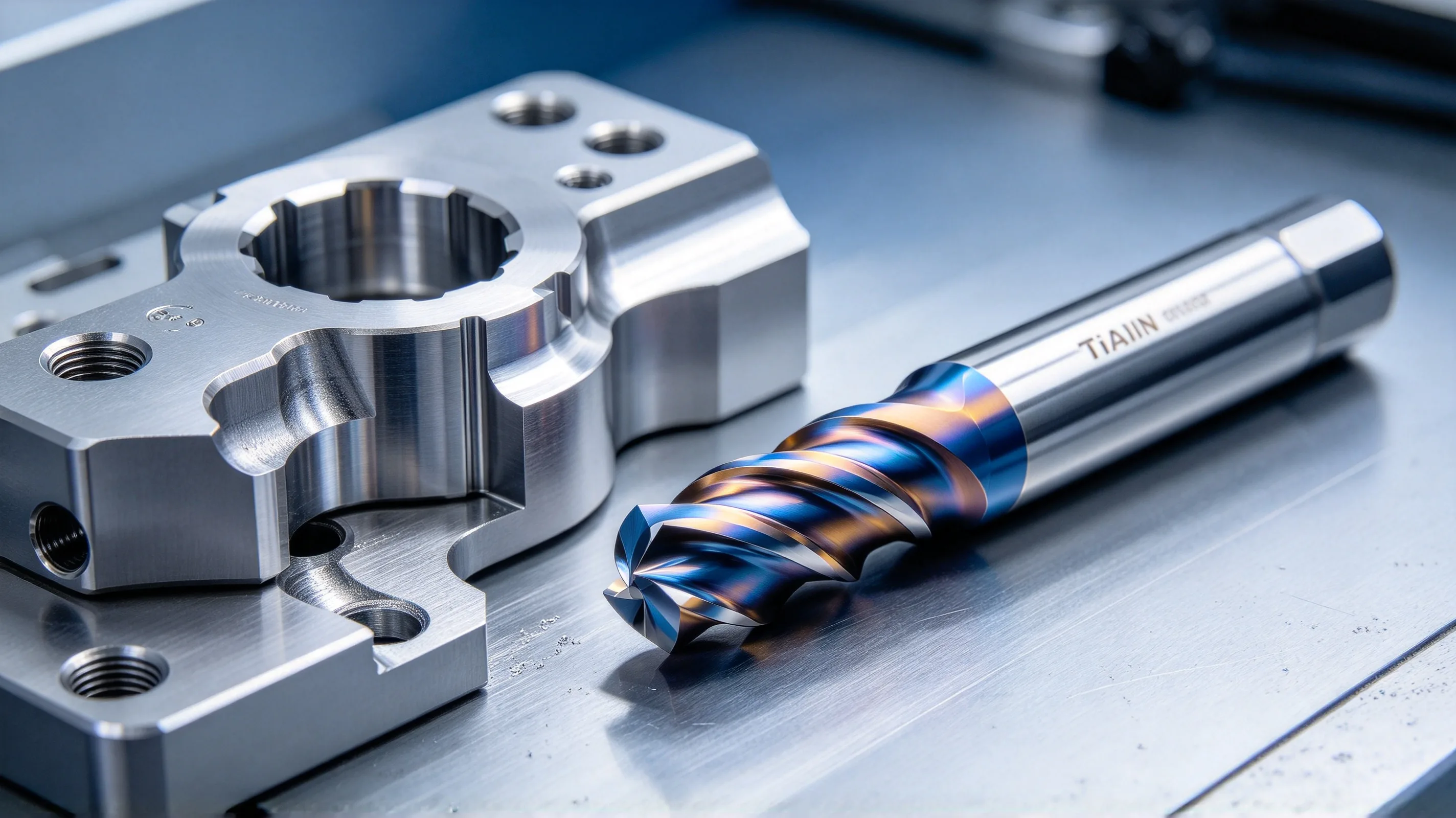
Tooling selection on titanium is one of the most underestimated variables in a CNC quote. A shop that runs the same end mills on titanium that it runs on aluminum or steel will burn through a tool inventory in a single shift and produce parts with surface-integrity problems that fail final inspection. A shop that runs the right tools at the right parameters will run the same end mill for 4–8 hours on titanium, with a stable surface finish and a predictable tool-change schedule. The difference is not the machine, the operator, or the coolant — it is the tooling decision that was made at the RFQ stage, before the spindle ever started.
This article works through the four tooling decisions that determine whether a titanium cycle is stable: carbide grade (per ISO 513), coating system, cutting-tool geometry, and tool-holder selection. It assumes the titanium machining processes guide as the top-level reference and the turning guide and drilling guide for the operation-specific tooling that has already been covered in detail — here we focus on the cross-cutting decisions (grade, coating, geometry, holder) that apply across milling, turning, and drilling. For the tool-wear failure modes that drive tool-replacement decisions, the tool wear causes and solutions article and the work hardening article cover the diagnostic side.
- Why tooling selection on titanium is not the same as for steel or aluminum
- ISO 513 carbide classification for titanium
- Coatings for titanium: TiAlN, AlTiN, TiSiN, CrAlN, CrN
- End mill selection for milling titanium
- Drill and tap selection (cross-link)
- Tool holder and runout
- Tool life management
- Tooling selection matrix
- Tooling checklist
Why tooling selection on titanium is not the same as for steel or aluminum
The cutting tool on a CNC machine has three jobs: penetrate the workpiece, evacuate the chip, and survive the heat. For steel and aluminum, the three jobs are easy to balance because the material gives the tool a wide operating window. Titanium collapses that window. Three material properties push the tooling decision toward a different balance than for any other alloy:
1. Low thermal conductivity forces a heat-resisting tool. Titanium’s thermal conductivity of about 7 W/m·K (versus 24 W/m·K for 304 stainless and 167 W/m·K for 6061 aluminum) means heat from the cut stays at the tool edge rather than dissipating through the chip. The cutting-edge temperature on a titanium end mill typically runs 200–300 °C higher than on the same tool in stainless at the same parameters. A tool that does not have a hot-hardness-stable grade and a high-temperature-stable coating will soften, wear, and fail in minutes.
2. High chemical reactivity forces a coated or low-cobalt tool. Above roughly 500 °C, titanium’s affinity for the cobalt binder in cemented carbide accelerates crater wear on the tool’s rake face. Uncoated carbide, or a high-cobalt grade, fails by dissolution rather than abrasion. A titanium-grade carbide uses lower cobalt content (typically 6–10%) and a coating that acts as a diffusion barrier between the tool and the hot chip.
3. Low elastic modulus forces a sharp, positive tool. Titanium’s modulus of about 110 GPa is roughly half that of steel. The workpiece deflects under cutting force, and the tool needs to slice rather than push — which means a sharper edge, a positive rake, and a geometry that keeps the radial component of the cutting force low. A tool that works on steel with a robust edge and a negative rake will rub rather than cut on titanium, and the rubbing generates the heat that accelerates every other failure mode.
The combined effect is that the right tooling for titanium is also the right tooling for the high-temperature end of the stainless spectrum — and the wrong tooling for aluminum, brass, and most general-steel work. A shop that stocks one carbide grade and one coating for all materials will find that grade fails in titanium long before it fails in steel. The cost of getting the tooling decision right is small (a 10–30% premium on the cutting tool); the cost of getting it wrong shows up as scrap, rework, and unstable cycle times.
ISO 513 carbide classification for titanium
The international standard for carbide grade classification is ISO 513, which assigns a letter-number code to each grade based on the application and the material to be cut. The codes are organised by workpiece material:
| Code | Material family | Color code (ISO 513) |
|---|---|---|
| P | Steel (long chipping) | Blue |
| M | Stainless steel (austenitic, martensitic, duplex) | Yellow |
| K | Cast iron, chilled cast iron | Red |
| N | Non-ferrous metals (aluminum, copper, brass) | Green |
| S | Heat-resistant superalloys (titanium, Inconel, Waspaloy, cobalt-chrome) | Orange |
| H | Hardened steel (> 45 HRC) | Grey |
Titanium is classified under S in ISO 513, alongside Inconel, Waspaloy, and other heat-resistant superalloys. Within each letter, a 01–50 number indicates the application range: lower numbers (S01, S05) are for finishing with high wear resistance, higher numbers (S30, S40) are for roughing with high toughness.
For titanium specifically, the relevant grades are:
- S05–S15: finishing grades with high wear resistance and low cobalt (3–6%). Used for finishing cuts on titanium at moderate Vc, where crater wear is the binding constraint.
- S20–S30: general-purpose titanium grades with medium cobalt (6–10%). The workhorse range for both roughing and finishing on most titanium work. This is the range that most “titanium-rated” carbide end mills, drills, and taps fall into.
- S35–S45: roughing grades with higher cobalt (10–15%) and tougher substrates. Used for heavy roughing on titanium where edge chipping is the binding constraint — typically interrupted cuts, cast surfaces, or heavy stock removal on tough beta alloys.
The classification matters because a tool labelled “titanium grade” can fall anywhere in the S range, and the wrong choice within S is as costly as the wrong letter. A shop that buys the cheapest “S” grade carbide and uses it for high-Vc finishing on Grade 5 will see rapid crater wear; a shop that buys the most wear-resistant S05 grade and uses it for roughing thin-wall features will see edge chipping.
Coatings for titanium: TiAlN, AlTiN, TiSiN, CrAlN, CrN
Coatings on carbide cutting tools for titanium do three things: provide a thermal barrier between the hot chip and the tool substrate, reduce friction at the tool-chip interface to lower cutting force, and act as a diffusion barrier against titanium’s chemical attack on the cobalt binder. The standard coating systems, named by their dominant chemistry:
- TiN (titanium nitride): the legacy coating. Stable to about 600 °C, moderate wear resistance, low cost. Used for general-purpose machining, but limited for titanium because the temperature stability is below the operating range of most titanium cuts.
- TiCN (titanium carbonitride): harder than TiN, with better wear resistance. Stable to about 700 °C. Useful for finishing on titanium, but increasingly replaced by TiAlN.
- TiAlN (titanium aluminium nitride): the workhorse coating for titanium. Stable to about 800 °C, excellent crater-wear resistance, good oxidation resistance. The default choice for general-purpose titanium tooling.
- AlTiN (aluminium-rich TiAlN): higher aluminium content shifts stability upward to about 900 °C, with improved hot-hardness. The preferred choice for high-Vc finishing and for hard titanium grades (STA condition, beta alloys).
- TiSiN (titanium silicon nitride): a nano-composite coating with very high hot-hardness and oxidation resistance. Stable to about 1000 °C. Used for finishing at high Vc, where crater wear is the binding constraint.
- CrAlN (chromium aluminium nitride): an alternative for shops that have had galling or built-up-edge issues with TiAlN in titanium. Lower friction coefficient, particularly useful for low-Vc finishing.
- CrN (chromium nitride): a thin, low-friction coating used for titanium parts that must avoid any contamination risk (medical implants, certain aerospace specs). Lower wear resistance than TiAlN or AlTiN but lower coefficient of friction.
- DLC (diamond-like carbon): amorphous carbon coating with extremely low friction. Used for aluminum and non-ferrous metals, occasionally for titanium where galling is severe. Limited to about 350 °C operating temperature, which makes it unsuitable for high-Vc titanium cuts.
The trade-off across all coating systems is hot-hardness versus toughness. The harder coatings (TiSiN, AlTiN) extend wear life at high temperature but chip at the edge if interrupted cuts are encountered. The tougher coatings (TiAlN, TiCN) tolerate interrupted cuts but wear faster at high Vc. For a general-purpose titanium operation on a rigid setup, TiAlN is the safe default. For finishing at high Vc on a rigid setup, AlTiN or TiSiN. For roughing on cast surfaces or interrupted cuts, TiAlN with a tougher substrate. The tool wear causes and solutions article covers the wear modes that drive coating selection in more detail.
End mill selection for milling titanium
End mill geometry for titanium follows the same logic as turning insert geometry, with the additional constraint of multi-tooth contact. The four geometry decisions that matter:
Flute count. A 4-flute end mill is the workhorse for general titanium milling, balancing chip space and core strength. A 3-flute mill is preferred for high-feed roughing on titanium because the wider flute clears chips better and reduces recutting. A 5-flute or 6-flute mill is used for finishing at high feed per tooth, but only on rigid setups with low radial engagement. A 2-flute mill is reserved for low-Vc aluminum-style work and is not appropriate for titanium.
Helix angle. A high-helix (45° or variable) end mill improves chip evacuation and reduces cutting force in titanium. The standard 30° helix works on rigid setups but generates more heat and is more prone to chatter on thin-wall features. A 45° helix or a variable-pitch helix (often called a “titanium-specific” geometry) is the preferred choice for any cut where chip evacuation or chatter is a concern.
Rake angle. Positive rake (5–10°) is standard for titanium. Negative rake, common in steel roughing, generates too much heat on titanium and accelerates crater wear. Some titanium end mills use a “double-positive” geometry (positive rake on both the axial and radial relief) for finishing on thin-wall features where the cutting force must be minimized.
Corner geometry. Square end mills (sharp corner) for roughing, corner-radius end mills (0.5–2.0 mm radius) for finishing. The corner radius improves surface finish and strengthens the cutting edge, but a larger radius on a finishing tool can pull the part toward the cutter if the setup is not rigid, producing an unwanted taper on thin-wall features.
Variable-pitch end mills (also called unequal-spaced or “titanium-rated” end mills) are increasingly the default for titanium. The unequal flute spacing breaks up the harmonic resonance that causes chatter, allowing higher feed rates and deeper cuts without chatter. The 5-axis titanium machining best practices article covers the trochoidal and adaptive-clearance toolpath strategies that pair with variable-pitch tools for high-efficiency titanium milling.
Drill and tap selection (cross-link)
Drill and tap selection for titanium is covered in detail in the operation-specific articles. The summary:
-
Drills: use coolant-through carbide drills (per ISO 5419) with 130–140° point angle and TiAlN or AlTiN coating for any diameter above 3 mm. Below 3 mm, use solid carbide with web thinning. The full drill selection by depth class and the parameter table are in the drilling guide.
-
Taps: use spiral-point taps (for through holes) or spiral-flute taps (for blind holes) in HSS-E or solid carbide, with TiCN or TiAlN coating. The tap drill diameter should target 60–65% thread percentage for titanium (versus 70–75% for steel), because the lower thread percentage reduces tap torque and breakage risk. For deep blind holes above 4×D, prefer thread milling over tapping to avoid tap breakage. The thread design article covers the full thread-form selection (UNJ, MJ, ISO metric), engagement length, and thread tolerance.
-
Reamers: use carbide reamers with TiAlN coating, with a 0.05–0.10 mm stock allowance on diameter. Do not use HSS reamers for titanium; the wear rate is too high to hold tolerance over a production run. Coolant-through reamers are preferred for any hole above 6 mm.
-
Boring tools: use indexable-insert boring bars with positive-geometry inserts in the same grade and coating as turning inserts. For finishing bores below 20 mm, use solid carbide boring bars with TiAlN coating. The boring bar overhang should not exceed 4×D to avoid chatter.
The cross-link pattern is intentional: the same carbide grade, the same coating, and the same insert geometry decisions apply across milling, turning, drilling, and tapping on titanium. A shop that standardises on a small set of qualified grades and coatings — typically S20–S30 grade with TiAlN coating for general work, S05–S15 with AlTiN or TiSiN for finishing — will run a more predictable tooling inventory than a shop that buys per-application specialty tools.
Tool holder and runout
The tool holder is half the tool. On titanium, a worn or poor-quality holder can ruin an otherwise qualified carbide end mill by introducing runout, vibration, or insufficient grip. The four holder parameters that matter most for titanium:
Runout. Total indicated runout (TIR) at the cutting edge should be ≤ 0.005 mm for general titanium milling and ≤ 0.003 mm for finishing at tight tolerance or for small-diameter tools. Runout above 0.01 mm on titanium causes uneven chip load on the cutting edges, accelerated wear on the heavy edge, and surface finish defects. A shrink-fit holder or a high-precision hydraulic holder (HSK or Coromant Capto) is the standard for titanium finishing; a standard ER collet can meet the 0.005 mm TIR spec only if the collet is new, the collet and nut are matched, and the holder is clean.
Grip. For titanium roughing, a shrink-fit holder or a hydraulic holder is preferred over a mechanical collet because the grip is more uniform around the tool shank and does not introduce the runout that an ER collet can develop at high cutting force. A worn or under-torqued ER collet on titanium will let the tool slip — usually without warning — and the resulting friction fit burns the tool shank and ruins the holder pocket. For high-Vc finishing, the same rule applies; a shrink-fit holder on a thermal shrink station is the standard for finishing end mills above 6 mm.
Balance. For tools running above 12,000 RPM, balance grade G2.5 or better is required. Unbalanced tools cause vibration, which on titanium shows up as chatter, accelerated wear, and poor surface finish. Most shrink-fit and hydraulic holders are balanced to G2.5 at the factory; mechanical collet holders typically need re-balancing after the collet is installed.
Holder length and overhang. The shorter the tool-holder assembly, the more rigid the cut. The standard rule is that the total overhang (tool plus holder nose) should not exceed 4× the tool diameter for roughing and 6× the tool diameter for finishing on rigid setups. A longer overhang on titanium is the most common cause of chatter and surface-finish defects that no parameter change can fix.
The cost of upgrading from a standard ER collet to a shrink-fit or hydraulic holder is roughly 5–10× per holder. The benefit, on titanium, is usually a 20–40% increase in tool life and a 10–20% increase in allowable cutting parameters. The payback on a titanium-dedicated cell is typically under 6 months.
Tool life management
Tool life on titanium is governed by two variables: cutting edge wear (flank wear and crater wear) and cutting-edge breakage (chipping and fracture). The replacement decision should be made on whichever variable hits its limit first. Three practices consistently work for managing tool life on titanium:
1. Document the wear-limit number for each tool. A standard “titanium end mill wear limit” might be 0.20 mm of flank wear measured at the corner; a “titanium drill wear limit” might be 0.10 mm of margin wear. Document the number on the setup sheet and replace the tool at the first measurement, not at the end of the cycle. Continuing to cut with a worn tool on titanium accelerates crater wear and produces a work-hardened layer that the next tool cannot cut.
2. Track parts per tool, not minutes per tool. On titanium, the binding constraint is parts per tool, not minutes. A tool that runs for 4 hours but only produces 6 parts is failing on parts, not on time. The setup sheet should list the target parts per tool and the action to take if the count is exceeded (typically, replace the tool and inspect the parts produced in the over-run window).
3. Inspect the chip, not the tool. The chip is the cheapest diagnostic on a titanium cycle. A stable cycle produces short, free-flowing straw-yellow chips. A cycle that produces long, stringy, blue or purple chips is failing before the tool wear is visible. Reading the chip catches the failure 5–15 minutes before the tool-wear measurement does, and at a fraction of the inspection cost. The chip control and fire prevention article covers the chip-evacuation discipline that pairs with tool life management.
For a tooling audit against a specific titanium program, the work hardening article covers the upstream factors (heat treatment, stock form, prior cold work) that accelerate tool wear and that the tooling decision has to absorb. The tool wear causes and solutions article covers the failure modes in detail.
Tooling selection matrix
The matrix below summarises the grade and coating choices for the most common titanium tooling decisions. Use it as a starting point; the right answer for a specific program is a function of the workpiece condition, the machine rigidity, and the lot size.
| Tool / operation | Workpiece condition | ISO 513 grade | Coating | Geometry | Holder |
|---|---|---|---|---|---|
| End mill, roughing | Grade 5 annealed | S20–S30 | TiAlN | 4-flute, 45° helix, positive rake | Shrink-fit or hydraulic, ≤ 0.005 mm TIR |
| End mill, roughing | Grade 5 STA or beta | S25–S35 | AlTiN | 4-flute, 45° helix, positive rake, tougher edge prep | Shrink-fit or hydraulic |
| End mill, finishing | Grade 5 annealed | S10–S20 | TiAlN or AlTiN | 4–6 flute, 45° helix, 0.5–1.0 mm corner radius | Shrink-fit, ≤ 0.003 mm TIR |
| End mill, finishing | Grade 5 STA or beta | S05–S15 | AlTiN or TiSiN | 4–6 flute, 45° helix, 0.5 mm corner radius | Shrink-fit, ≤ 0.003 mm TIR |
| Drill, Ø < 3 mm | Any | S15–S25 | TiAlN | Solid carbide, web thinned, 130–140° point | Collet acceptable |
| Drill, Ø 3–12 mm | Any | S20–S30 | TiAlN | Coolant-through, 130–140° point, parabolic flutes | Shrink-fit or hydraulic |
| Drill, Ø > 12 mm | Any | S25–S35 | AlTiN | Indexable-insert or extended-length coolant-through | Shrink-fit or hydraulic |
| Tap, M3–M16 | Any | HSS-E or carbide | TiCN or TiAlN | Spiral-point (through) or spiral-flute (blind), 60–65% thread | Tension/compression holder preferred |
| Reamer, Ø 6–25 mm | Any | S15–S25 | TiAlN | Carbide, 0.05–0.10 mm stock | Shrink-fit, ≤ 0.003 mm TIR |
| Turning insert, roughing | Grade 5 annealed | S20–S30 | TiAlN | CNMG/DNMG, MR chipbreaker, 0.8 mm nose | Standard turning holder |
| Turning insert, finishing | Grade 5 annealed | S10–S20 | TiAlN or AlTiN | VNMG/DNMG, PM chipbreaker, 0.4–0.8 mm nose | Standard turning holder |
| Boring bar, Ø < 20 mm | Any | S15–S25 | TiAlN | Solid carbide, positive geometry | Shrink-fit |
The matrix is a starting point, not a fixed recipe. The right tooling for a specific titanium program depends on the machine, the lot size, the workpiece condition, and the operator’s experience. The next section’s checklist is a more practical decision aid for the day-to-day.
Tooling checklist
- Specify ISO 513 grade S for all cutting tools on titanium. Use S05–S15 for finishing, S20–S30 for general work, S30–S40 for roughing on tough grades.
- Default coating to TiAlN. Use AlTiN or TiSiN for high-Vc finishing, CrAlN for low-Vc finishing where galling is a concern, CrN for medical or contamination-sensitive work.
- Use 4-flute end mills with 45° helix and positive rake as the default. Switch to 3-flute for high-feed roughing, 5–6 flute for high-feed finishing on rigid setups.
- Specify coolant-through drills (per ISO 5419) with 130–140° point angle for any diameter above 3 mm. Order as coolant-through, do not retrofit.
- Use positive-geometry turning inserts with PM chipbreaker for finishing and MR chipbreaker for roughing. Match the insert shape (CNMG/DNMG/VNMG) to the feature accessibility.
- Hold TIR ≤ 0.005 mm for general titanium milling, ≤ 0.003 mm for finishing. Use shrink-fit or hydraulic holders; verify ER collet runout before each use.
- Limit total tool overhang to 4×D for roughing, 6×D for finishing on rigid setups.
- Balance tools above 12,000 RPM to G2.5 or better.
- Document the wear-limit number (e.g., 0.20 mm flank wear, 0.10 mm margin wear) on the setup sheet. Replace the tool at the first measurement.
- Track parts per tool, not minutes per tool. Replace the tool when the parts count is reached, regardless of cycle time.
- Read the chip at the start of the cycle and after any parameter change. Short straw-yellow chips indicate a stable process; long stringy or blue chips indicate a problem.
- For deep holes (above 8×D) or hard grades (STA, beta), use gun drills, BTA drills, or indexable-insert drills rather than extended-length solid carbide.
For a tooling review against a specific titanium program, send the STEP file and the print to the RFQ intake; the engineering team returns a manufacturability feedback with tooling, parameter, and toolpath recommendations. The 5-axis titanium machining services and engineering review capability at Boze review every titanium RFQ against the checklist above before any tooling is ordered, and the typical outcome is a tooling pass that surfaces 1–2 grade or coating mismatches per program. For Ti-6Al-4V Grade 5 parts in particular, the tooling decision is what determines whether the part runs on a 3-axis mill, a 5-axis cell, or a dedicated titanium machining cell — and that decision drives the rest of the cycle time.