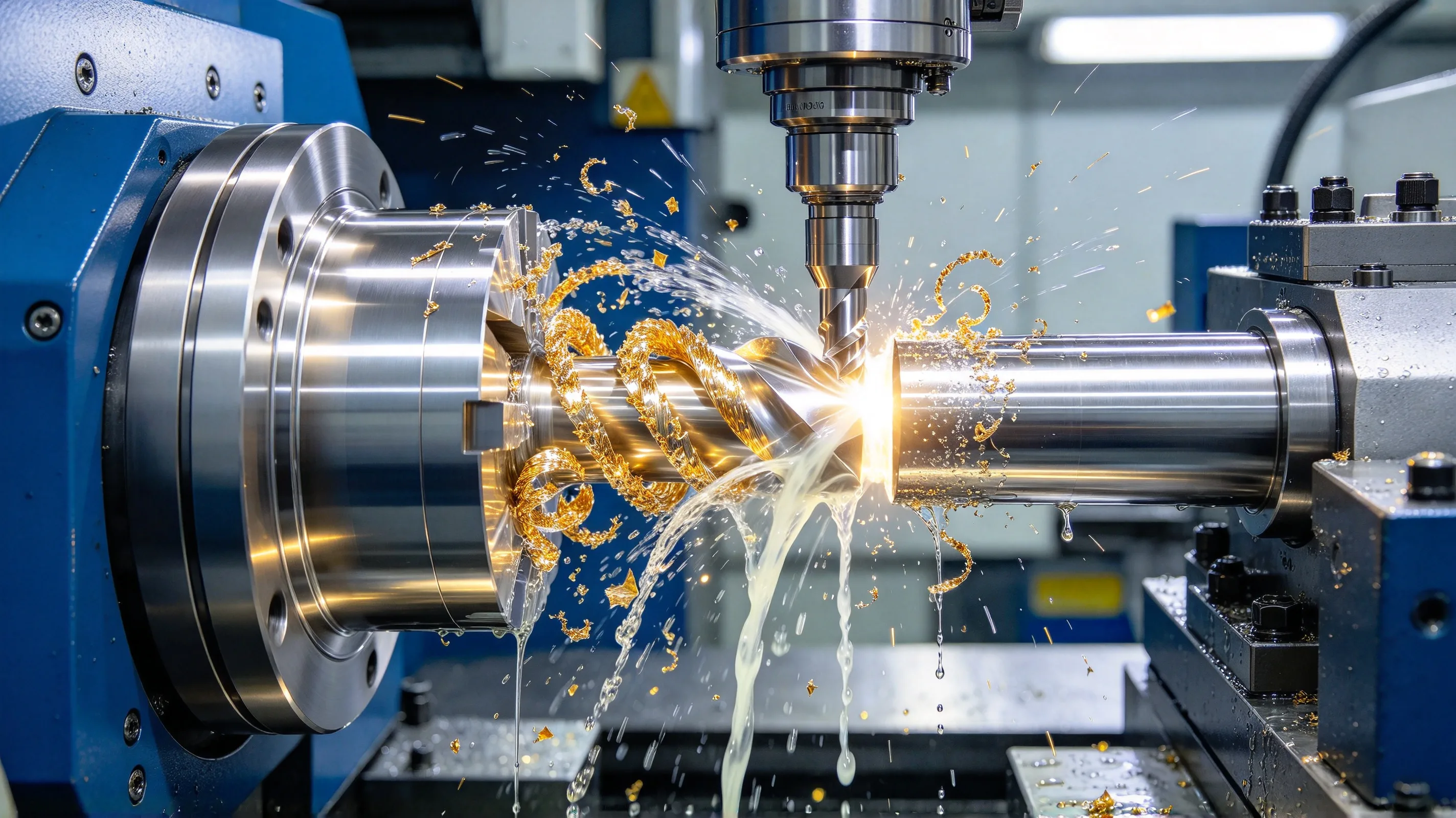
Turning titanium is one of those operations where the same insert and the same parameters that run cleanly for 200 parts in 17-4PH stainless will be destroyed in 8 parts in Ti-6Al-4V. The physics is not subtle. Titanium’s thermal conductivity runs around 7 W/m·K — roughly a third of 304 stainless and a tenth of carbon steel — so almost all the heat generated at the cutting edge stays in the insert rather than dissipating through the chip or the workpiece. The chemical reactivity of titanium at elevated temperature then accelerates crater wear on the insert’s rake face and promotes built-up edge (BUE) at low speeds, which in turn smears onto the part surface and wrecks surface finish. The result is a narrow process window between “too slow, BUE” and “too fast, crater wear” that is tighter than for almost any other aerospace alloy.
This article works through the four process decisions that determine whether a titanium turning operation is stable: insert geometry, carbide grade and coating, cutting parameters, and chip control. It assumes the titanium machining processes guide as the top-level reference and the titanium chip control and fire prevention article for chip-evacuation safety as background — those cover the cross-process view; here we focus on turning specifically, and the parameters and tooling choices that distinguish a stable cycle from a burning one. For the thermal-mechanics rationale behind the parameter choices, the why titanium is difficult to machine article covers the heat-concentration physics in detail.
- Why turning titanium is a different game than turning steel
- Insert geometry: rake angle, chipbreaker, nose radius for titanium
- Carbide grade and coating for titanium turning
- Cutting parameters: Vc, fn, ap for titanium
- Chip control: shape, evacuation, color warning signs
- Coolant and chip-evacuation strategy
- Workholding and fixturing for turning titanium
- Common turning defects and fixes
- Turning parameter reference
- Turning checklist
Why turning titanium is a different game than turning steel
Three material properties set titanium turning apart from steel turning, and all three push the process toward tighter parameter windows:
1. Low thermal conductivity. Ti-6Al-4V conducts heat at roughly 7 W/m·K, versus 24 W/m·K for 304 stainless and 50 W/m·K for AISI 1045 carbon steel. With less heat leaving through the chip, the insert’s cutting edge sees a higher temperature for a given combination of speed and feed — typically 50–100 °C hotter than the same insert in stainless at the same parameters. The insert’s hot-hardness and coating stability therefore matter more than in steel, where the chip is doing more of the heat-removal work.
2. High chemical reactivity at temperature. Above roughly 500 °C, titanium’s affinity for the cobalt binder in cemented carbide accelerates crater wear on the insert’s rake face — a failure mode that does not appear in steel turning at the same parameters. Combined with the low conductivity, this means the upper bound on Vc is set by crater wear and diffusion, not by plastic deformation of the insert.
3. Low elastic modulus and high strength at temperature. Titanium’s modulus (about 110 GPa for Ti-6Al-4V) is roughly half that of steel, so thin-wall rotational features deflect under clamping pressure and under cutting load. The deflection changes effective depth of cut mid-pass, which in turn changes cutting force, which deflects the part more — a positive-feedback loop that shows up as taper, ovality, or chatter on parts that were rigid at the design stage.
The combination forces a different operating envelope: speeds are typically 30–50% lower than in stainless turning, feeds are tuned more carefully to keep chip thickness in the range the insert geometry was designed for, and coolant delivery is treated as a process parameter rather than an afterthought. A shop that runs titanium at the same Vc and fn as 17-4PH will burn inserts and reject parts in a single shift; a shop that runs titanium at the parameters the insert manufacturer publishes, with chip control and high-pressure coolant in place, will run the same insert for a full shift on a stable cycle.
Insert geometry: rake angle, chipbreaker, nose radius for titanium
Insert geometry controls three things in a titanium turning operation: cutting force, chip shape, and surface finish. Each is tuned by a different feature of the insert.
Rake angle. Positive rake reduces cutting force and heat generation, which extends insert life on titanium. Most titanium turning uses inserts with positive rake in the 5–15° range, with finishing operations typically at the higher end (more positive) and roughing at the lower end (less positive for edge strength). Negative-rake inserts, common in heavy steel roughing, are not used for titanium because the cutting force they generate exceeds the elastic limit of the thin-section features typical in titanium aerospace and medical parts.
Chipbreaker geometry. The chipbreaker must form the chip into a shape that clears the cut without wrapping around the part or packing in the insert pocket. For titanium, the typical chipbreaker is a narrower, more open design than for steel — wide enough to curl the chip, open enough to avoid packing. The standard ISO nomenclature (per ISO 242) for chipbreaker styles in titanium turning includes “PM” (positive-medium, for finishing), “PR” (positive-roughing, for medium removal), and “MR” (medium-roughing, for heavier passes). Inserts that produce a long stringy chip in titanium are dangerous because the string can wrap the spindle, the chuck, or the operator’s glove — and titanium chips are ignition sources if they accumulate.
Nose radius. Nose radius affects surface finish and cutting force in opposite directions: a larger nose radius (0.8 mm, 1.2 mm) gives a better surface finish and stronger edge, but increases radial cutting force and the risk of chatter on thin-wall features. A smaller nose radius (0.4 mm, 0.8 mm) reduces chatter risk but degrades surface finish. The typical rule for titanium: use 0.4–0.8 mm nose radius for roughing and 0.8–1.2 mm for finishing, with the upper end reserved for rigid setups and the lower end for thin-wall or long-reach features. The design guide for titanium parts and the thin-wall turning article cover the part-design side of this trade-off.
Standard insert shapes used in titanium turning include CNMG, DNMG, and WNMG for medium-to-heavy roughing; VNMG for profiling and finishing; and CCMT or DCMT for finishing on smaller-diameter features. The shape choice is driven by the accessibility of the feature and the depth of cut required, not by the material — titanium does not change the shape selection, but it does change the chipbreaker and grade.
Carbide grade and coating for titanium turning
Carbide grade selection for titanium turning follows the ISO 513 classification. The relevant categories for titanium are:
- ISO K10–K20: fine-grain cemented carbide with low cobalt content (3–6%). High wear resistance but lower toughness. Used for finishing titanium at moderate parameters.
- ISO K20–K30: medium-grain carbide with mid-range cobalt (6–10%). The workhorse range for general-purpose titanium turning, balancing wear life and edge strength.
- ISO S10–S20: sub-grade or specialty grades designed specifically for titanium and other difficult-to-machine alloys. Often a tougher substrate with a wear-resistant coating, optimised for the high-temperature crater-wear regime of titanium machining.
Coatings change the picture. Uncoated carbide is rarely used for titanium turning because the uncoated tool has no diffusion barrier between the cobalt binder and the hot titanium chip. The standard coating systems, named by their dominant chemistry, are:
- TiAlN (titanium aluminium nitride): the workhorse coating for titanium. Stable to roughly 800 °C, good crater-wear resistance, and reasonable cost.
- AlTiN (aluminium-rich TiAlN): higher aluminium content shifts stability upward to roughly 900 °C, useful for high-Vc finishing or for grade 5 in the solution-treated-and-aged (STA) condition.
- TiSiN (titanium silicon nitride): a nano-composite coating with very high hot-hardness. Best for finishing at high Vc, where crater wear would otherwise limit tool life.
- CrAlN: an alternative for shop floors that have had galling issues with TiAlN-coated tools in titanium; less common but available from most major suppliers.
The trade-off is that harder coatings extend wear life but tend to chip at the edge if interrupted cuts are encountered. For titanium aerospace turned parts, which are often finish-turned from a roughed forging with a continuous chip, the harder coating wins. For medical or small-diameter parts where the cut engages and disengages the workpiece (undercut features, keyways), a tougher coating or a smaller edge prep is the safer choice. The tool wear causes and solutions article covers the failure modes in more detail.
Cutting parameters: Vc, fn, ap for titanium
The starting parameters for titanium turning are roughly half those used in 17-4PH stainless turning, and the rationale comes back to the thermal story: at the same Vc, the insert sees a higher temperature in titanium than in stainless, so the wear-limited speed is lower. The starting points below assume a positive-rake TiAlN-coated insert in K20–K30 grade, and a rigid setup on a modern CNC lathe or mill-turn. Always derate 20% for the first article and tighten once tool-wear data confirms.
| Operation | Vc (m/min) | fn (mm/rev) | ap (mm) | Notes |
|---|---|---|---|---|
| Rough turning, Grade 5 annealed | 40–60 | 0.20–0.30 | 2.0–4.0 | Use MR chipbreaker, 0.8 mm nose radius |
| Rough turning, CP Grade 2 | 60–90 | 0.20–0.30 | 2.0–4.0 | CP grades are roughly 30% more machinable than Grade 5 |
| Rough turning, Grade 5 STA | 30–45 | 0.15–0.25 | 1.5–3.0 | Solution-treated condition is harder and less machinable |
| Finish turning, Grade 5 annealed | 60–90 | 0.08–0.15 | 0.3–0.8 | Use PM chipbreaker, 0.4–0.8 mm nose radius |
| Finish turning, CP Grade 2 | 90–130 | 0.10–0.20 | 0.3–1.0 | Higher Vc is acceptable in CP grades |
| Finish turning, Grade 5 STA | 45–70 | 0.08–0.12 | 0.2–0.6 | Keep Vc at the low end of the band to control heat |
| Profiling / contour turning | 40–60 | 0.05–0.10 | 0.2–0.5 | Reduce Vc by 20% from finishing, hold low ap |
| Parting / cutoff | 30–50 | 0.05–0.10 | — | Use dedicated grooving insert, high-pressure coolant |
The numbers are deliberately bands, not fixed values. Three things move the actual setting: the machine’s spindle power and torque at the working RPM, the insert’s nose radius and edge prep, and the rigidity of the setup (chuck pressure, tail-stock support, overhang length). A shop running a 7.5 kW lathe on a 50 mm diameter part will hold the upper end of the band; a shop running a 3-axis mill in lathe-mode on the same part will run the lower end.
Two common parameter mistakes to avoid: Vc set by the spindle’s maximum RPM rather than by the wear envelope (the spindle will go to 5,000 RPM, but the insert will not), and fn set too low to “be safe” (low fn promotes BUE in titanium, which wrecks surface finish and accelerates notch wear at the depth-of-cut line).
Chip control: shape, evacuation, color warning signs
Chip shape is the cheapest real-time diagnostic on a titanium turning operation. Read the chip, and you read the process.
Chip shape as a process signal. The target chip shape in titanium turning is a short, free-flowing comma or loose coil — what the standard ISO 3685 nomenclature calls “acceptable” chips (segments 1–3 in the chip classification). A long, stringy, ribbon-like chip (segments 4–6) means the feed is too low, the chipbreaker geometry is too open, or the Vc is in the BUE regime — the chip is welding to the insert and tearing off in long segments, which produces a poor surface finish and accelerates notch wear. A blue or purple chip (instead of the target straw-yellow or light-blue) means the temperature at the cutting edge has exceeded the coating’s stability range, and the insert is about to fail. A powdery, segmented chip with a dark blue or grey colour means crater wear is advanced and the insert must come out now, not at the next tool change.
The shop-floor rule: read the chip before the surface finish. By the time the part surface shows signs of a problem, the insert has typically been running in a bad state for 5–15 minutes. The chip tells you in seconds.
Evacuation. A chip that does not clear the cut is a chip that will pack, recut, and ignite. In titanium turning, chip evacuation failures are the most common cause of fire events, particularly on parts where the chip is trapped in a recess or against a shoulder. Three rules apply:
- Aim the chip downward and away from the spindle, the chuck, and the operator station. A chip conveyor or chip pan is not optional on a titanium lathe.
- Never let a chip nest in a recess. Peck the part off the chuck, blow out the recess, and resume.
- For deep-reach features (long shafts, narrow diameters), use a chip-breaker insert geometry that produces a tight coil, not a long ribbon. A long ribbon will wrap the spindle.
The titanium chip control and fire prevention article goes deeper into the fire-prevention and chip-handling protocols that apply across all titanium machining operations, not just turning.
Coolant and chip-evacuation strategy
Coolant in titanium turning does three things, in order of importance: it removes heat from the cutting zone, it lubricates the tool-chip interface to reduce BUE, and it evacuates chips from the cut. Standard flood coolant (a 5–10% emulsion at 10–30 L/min) handles lubrication adequately for finishing cuts, but it does not remove heat effectively at the cutting edge because titanium’s low thermal conductivity keeps the heat at the interface. High-pressure coolant (70–150 bar, applied through the tool or through a dedicated nozzle directed at the cut) is the standard for titanium roughing and for any cut where heat removal is the binding constraint.
The practical rules:
- Flood alone is acceptable for finishing at moderate Vc and ap, where chip load is low and the heat input is manageable.
- High-pressure coolant is required for roughing, particularly for depths of cut above 2 mm, where the heat input overwhelms what flood can carry away.
- Through-tool coolant is preferred where the holder supports it. It directs the jet exactly at the rake face, where heat removal matters most.
- Coolant concentration should be held at 8–12% for titanium (slightly higher than for steel). The emulsion’s lubricity matters more in titanium because of the BUE risk; lower concentrations starve the lubricant film.
- Coolant filtration to 50 µm or finer. Titanium chips are small and abrasive; a dirty coolant tank acts as a grinding slurry on every insert that passes through it.
The high-pressure coolant strategy article covers coolant pressure, filtration, and concentration in more detail, including the nozzle and through-tool-holder selection for mill-turn cells.
Workholding and fixturing for turning titanium
Workholding is half of the turning problem on titanium, and the part that is most often short-changed on the shop floor. The two failure modes are deflection (the part bends under cutting load, producing taper and ovality) and clamping damage (the chuck pressure marks the surface or work-hardens the area in front of the cut).
For solid bar / forging billets: A 3-jaw power chuck with hard top jaws is the standard. Set chuck pressure to the minimum that prevents slippage — typically 8–15 bar on a hydraulic chuck for a 50–100 mm diameter billet. Over-pressure is the most common cause of chuck-induced ovality, particularly on thin-wall tubular stock. For longer parts, use a tail stock with a live center; do not rely on the chuck alone for length-to-diameter ratios above 3:1.
For thin-wall tubular or near-net-shape parts: A mandrel expands inside the part and supports the wall from within. The mandrel must be sized to within 0.02–0.05 mm of the part’s nominal ID, and the expansion must be controlled (a hydraulic mandrel is preferred over a mechanical wedge for repeatability). Without internal support, a thin-wall titanium part will deflect 0.1–0.3 mm under cutting load, which is typically more than the dimensional tolerance allows.
For finished or semi-finished parts that must be held without marking: A collet chuck (5C, 16C, or step-collet) is the standard. Collet pressure is distributed over a longer axial length than a 3-jaw chuck, which reduces local deflection and avoids the localised work-hardening that a 3-jaw chuck can produce on a finished surface.
For long shafts (L/D above 4:1): A steady rest is required. The steady rest supports the part at a mid-span location and limits deflection to within the cutting tolerance; without it, a long titanium shaft will chatter at the tool tip and produce a wavy surface finish that no finishing pass can remove.
The titanium deformation causes and prevention article covers the broader workholding and stress-relief story for parts that come off the machine with a residual distortion problem.
Common turning defects and fixes
The defect-to-cause table below covers the seven failure modes that show up most often on titanium turning cycles. Each row is something we see in first-article runs at our shop, with the cheapest fix that does not require re-cutting the part.
| Symptom | Most likely cause | First fix |
|---|---|---|
| Blue or purple chip, rapid insert wear | Vc too high, coolant pressure too low, or coating outside its stability range | Reduce Vc by 15–20%; verify high-pressure coolant is reaching the cut; switch to AlTiN or TiSiN coating |
| Built-up edge (BUE) — smearing on the insert and part | Vc too low, fn too low, or rake angle too negative | Increase Vc by 10–15%; increase fn by 0.02–0.05 mm/rev; switch to a more positive rake insert |
| Chatter on a thin-wall or long-reach feature | Insufficient rigidity, nose radius too large, or excessive overhang | Reduce nose radius to 0.4 mm; add a steady rest; reduce ap and radial engagement by 30% |
| Taper on a long shaft (large end at the chuck) | Part deflection under cutting load | Add tail-stock support; reduce ap; switch to a finishing pass with lighter depth |
| Ovality on a thin-wall tubular part | Excessive chuck pressure or insufficient mandrel support | Reduce chuck pressure to 8–10 bar; verify mandrel expansion is uniform; consider a hydraulic mandrel |
| Surface roughness exceeds spec | Built-up edge; worn insert; insufficient coolant; or incorrect nose radius | Replace insert; verify coolant concentration ≥8%; increase nose radius to 0.8 mm if chatter is not a concern |
| Notch wear at the depth-of-cut line | Insert geometry, BUE, or work-hardening from a previous operation | Use a stronger edge prep (e.g., T-land); ensure previous heat treatment is uniform; check for case-hardened layer from upstream forming |
| Part runs oversize at the end of a finishing pass | Thermal growth during the cut, or springback after the tool passes | Add a dwell-and-measure step; reduce finishing Vc; consider a stress-relief operation between roughing and finishing |
The single most useful diagnostic is to take a part off the machine mid-cycle, before the cycle is finished, and read the chip. A stable titanium turning cycle produces a short, free-flowing straw-yellow chip. Anything else is a process signal that the cycle is drifting, and the cost of stopping to investigate is a fraction of the cost of scrapping the part at final inspection.
Turning parameter reference
The card below condenses the parameter table in Section 4 to a one-line-per-case format suitable for posting at the machine. Use it as a starting point; the bands reflect typical shop-floor conditions and should be tightened or loosened based on first-article results and tool-wear data.
| Material / condition | Operation | Vc (m/min) | fn (mm/rev) | ap (mm) | Insert class |
|---|---|---|---|---|---|
| Grade 5 annealed | Rough | 50 | 0.25 | 3.0 | K20–K30, TiAlN, MR chipbreaker |
| Grade 5 annealed | Finish | 75 | 0.12 | 0.5 | K10–K20, TiAlN, PM chipbreaker |
| Grade 5 STA | Rough | 38 | 0.20 | 2.0 | K20–K30, AlTiN, MR chipbreaker |
| Grade 5 STA | Finish | 55 | 0.10 | 0.4 | K10–K20, AlTiN or TiSiN, PM chipbreaker |
| CP Grade 2 | Rough | 75 | 0.25 | 3.0 | K20–K30, TiAlN, MR chipbreaker |
| CP Grade 2 | Finish | 110 | 0.15 | 0.5 | K10–K20, TiAlN, PM chipbreaker |
| Grade 23 ELI (Ti-6Al-4V ELI) | Rough | 45 | 0.22 | 2.5 | K20–K30, TiAlN, MR chipbreaker |
| Grade 23 ELI (Ti-6Al-4V ELI) | Finish | 65 | 0.10 | 0.4 | K10–K20, TiAlN, PM chipbreaker |
| Beta alloys (Ti-10V-2Fe-3Al, Ti-5553) | Rough | 30 | 0.18 | 1.5 | S10–S20, AlTiN, MR chipbreaker |
| Beta alloys | Finish | 45 | 0.10 | 0.3 | S10–S20, AlTiN, PM chipbreaker |
The reference values are conservative — derate further for thin-wall features, interrupted cuts, or weak setup rigidity. Beta alloys deserve a separate note: their machinability rating is roughly 60% of Grade 5, and the lower Vc/fn range is mandatory rather than advisory.
Turning checklist
- Use positive rake inserts in K20–K30 grade with TiAlN or AlTiN coating for general-purpose titanium turning; reserve TiSiN for high-Vc finishing.
- Match chipbreaker geometry to the operation: PM for finishing, PR for medium roughing, MR for heavy roughing.
- Set Vc to the lower end of the published band on the first article and tighten only after tool-wear data confirms stability.
- Hold fn at the upper end of the band; low fn promotes BUE in titanium.
- Use high-pressure coolant (70–150 bar) for any roughing cut above 2 mm ap, or for any cut where chip evacuation is constrained.
- Hold coolant concentration at 8–12% and filtration at 50 µm or finer.
- Set chuck pressure to the minimum that prevents slippage; over-pressure produces ovality on thin-wall parts.
- Add a tail stock for L/D above 3:1; add a steady rest for L/D above 4:1.
- For thin-wall tubular parts, use a mandrel and verify expansion is uniform.
- Read the chip before the surface finish. Short straw-yellow is good; long stringy or blue is bad.
- Stop the cycle if the chip color changes from straw to blue/purple, or if chatter appears; replace the insert and verify the cause before resuming.
For a turning parameter review against your specific part geometry, send the STEP file and the rough-stock spec to the RFQ intake; the engineering team returns a manufacturability feedback with insert, parameter, and workholding recommendations. The 5-axis titanium machining services and engineering review capability at Boze review every turning and mill-turn RFQ against the checklist above before any tooling is ordered, and the typical outcome is a parameter pass that surfaces 1–2 over-aggressive Vc settings per program. For Ti-6Al-4V Grade 5 parts in particular, the turning parameter set is what determines whether the part runs on a 2-axis lathe, a mill-turn cell, or a dedicated turning center with a sub-spindle — and that decision drives the rest of the cycle time.